Sighting Mechansim For Fire Arms

a technology of sighting mechanism and firearm, which is applied in the direction of sighting devices, weapon components, aiming means, etc., can solve the problems of high mechanical effort of the sighting telescope, the difficulty of achieving high hitting accuracy using a sole optical sighting mechanism, and the high cost of the corresponding sighting telescope, so as to achieve high flexibility in operation and reduce the unit cost

Active Publication Date: 2008-07-10
KOCH RUDOLF +2
View PDF21 Cites 71 Cited by
  • Summary
  • Abstract
  • Description
  • Claims
  • Application Information

AI Technical Summary

Benefits of technology

[0019]It is therefore the an object of the present invention to create a sighting mechanism that avoids the disadvantages referred to above and ensures very high hitting precision even over long and very long shooting distances, whereby both influences on the trajectory of the projectile from the external environment and from the discharged ammunition and / or influences originating from the weapon are accounted for reliably and whereby the handling of the sighting mechanism and of the weapon by a marksman shall be as simple as possible.

Problems solved by technology

With regard to firearms for large shooting distances, e.g., rifles for shooting distances of 1000 m and more, it is difficult to achieve high hitting accuracy using a solely optical sighting mechanism, such as a sighting telescope.
The sighting telescope described therein requires a high mechanical effort since, on the one hand, it has to be so smooth-operating while being exactly connected to the weapon that it can be re-adjusted exactly by the micromotor or micromotors, and, on the other hand, withstands the recoil forces upon the discharge of a shot without being damaged.
These requirements can be met only through a high fine-mechanical effort which renders the weapon and the corresponding sighting telescope very expensive.
Moreover, it is possible to correct for only some of the influences interfering with the trajectory of the projectile such that the hitting accuracy is improved, but not yet optimal.
However, this known sighting telescope cannot correct further influences, in particular influences of the external environment, such as the distance between the weapon and the target.
As before, the re-adjustment proceeds by means of two adjustment motors of this known sighting telescope which necessitates a very high mechanical effort and leads to a high sensitivity to external mechanical influences.
However, the sighting mechanism in this case disadvantageously comprises but a single sighting optics that is directed to be parallel to the barrel of the weapon and that is combined with a camera.
It is another disadvantage that the quality of the image recorded by the camera that is displayed on the screen deteriorates, in particular, with increasing target distances, which makes the aiming more difficult for the marksman.
It is considered to be disadvantageous that the image recorded by the camera gradually deteriorates with increasing shooting distances, which makes aiming more difficult, in particular over large distances.
Moreover, no clues are provided herein as to how to take into account environmental parameters that influence the trajectory of the discharged projectile from outside.
Accordingly, the sighting mechanism described in this document provides optical support to the marksman in the process of aiming in that a trajectory is optically displayed to the marksman, but high hitting accuracy, in particular at larger shooting distances, cannot be attained with this.

Method used


Image

  • Sighting Mechansim For Fire Arms
  • Sighting Mechansim For Fire Arms

Examples


Embodiment Construction

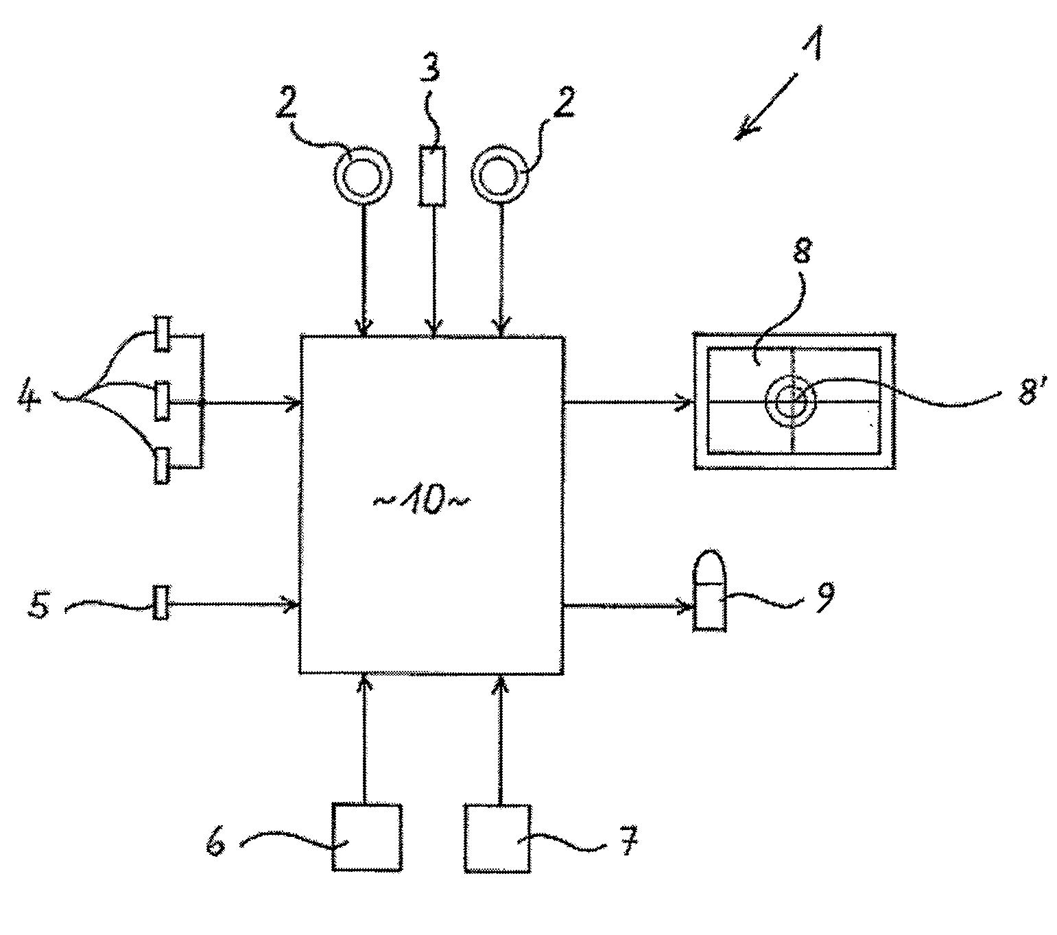
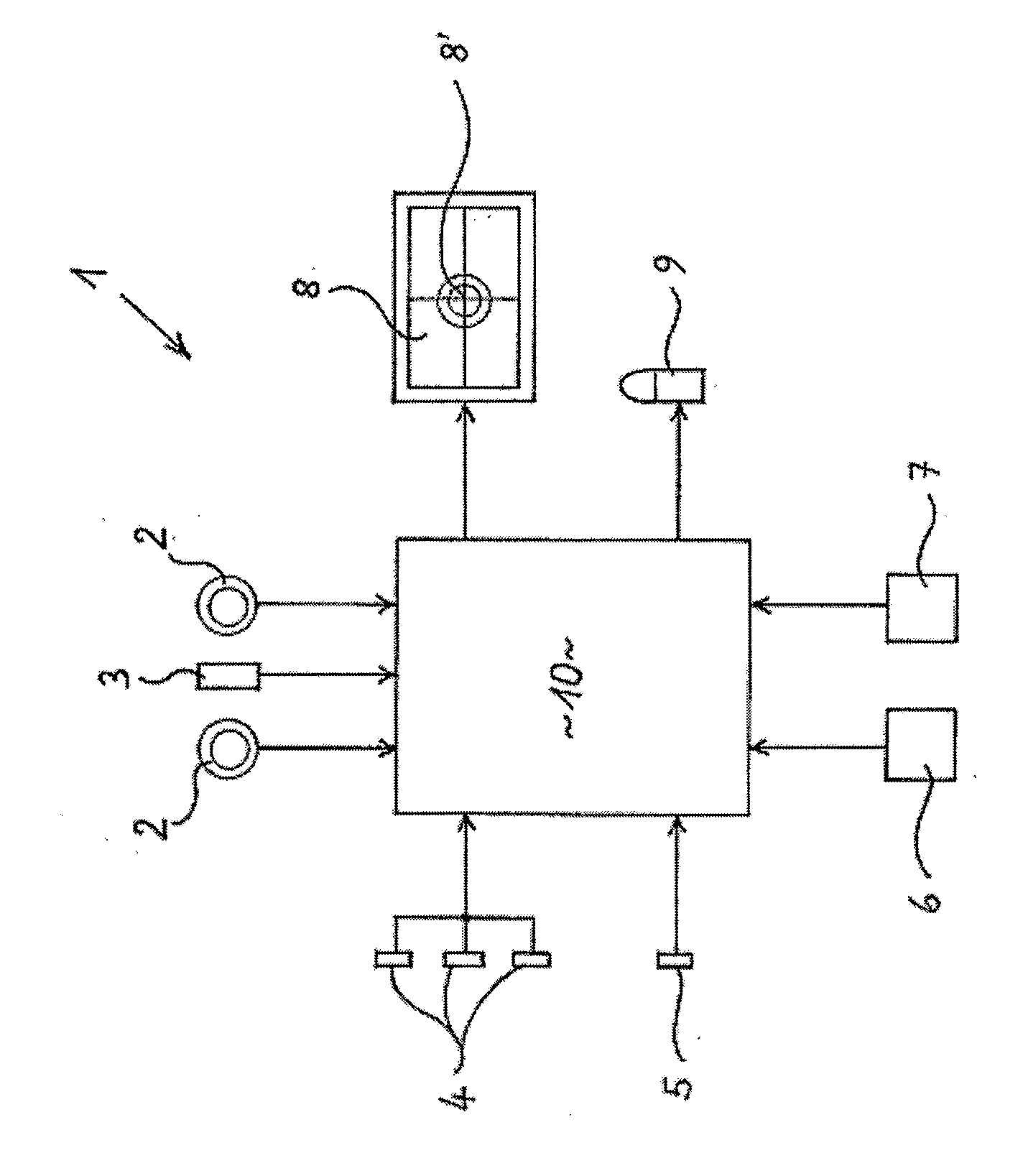
[0051]The sighting mechanism 1 that is shown schematically in the drawing comprises multiple components that are connected to a central digital computer unit 10 either electrically by cable or wireless. The sighting mechanism 1 and its components are jointly attached to a weapon that is not shown here, or they are integrated into that weapon. Alternatively, the parts of the sighting mechanism can also be attached to or arranged on partly the weapon and partly a marksman operating the weapon, whereby the parts again are in communication contact with each other either by cable or wireless.

[0052]The top part of the drawing shows two digital video cameras 2 that are arranged parallel to each other and are attached, for example, to the barrel of a corresponding weapon and simultaneously record the same target area. The video cameras 2 are connected to the computer unit 10 by means of a suitable input interface each. Accordingly, the cameras 2 synchronously deliver two images of an aimed-...


PUM


Abstract

A sighting mechanism for a firearm, including a video camera, a video screen, a digital sighting distance meter, at least one sensor for measuring environment, cartridge and / or weapon parameters, at least one biometric sensor, at least one memory module for biometric data and / or munitions data and a digital computer. The sighting device includes at least two video cameras arranged in a parallel manner in relation to each other to capture the target sighting field. The computer has at least two video input points and an image processing unit enabling the video image data to be superimposed in real time in a pixel precise manner in relation to the target field and to be reproduced on the screen. The computer includes a ballistic computer which enables the target image to reproduced on the screen. A graticule, which is arranged in the superimposed screen or on the screen, can be positioned in an automatic manner and in real time according to the incoming data, such that the position of the graticule in the target field corresponds to a real projectile point of impact.

Description

BACKGROUND OF THE INVENTION[0001]The present invention relates to a sighting mechanism for a firearm, having the following features:[0002]a digital video camera that is arranged on a firearm parallel to its barrel and records a target sighting field,[0003]a video screen that is arranged in the sighting field of a marksman operating the firearm and displays a target image that is recorded by the video camera,[0004]a digital target distance meter,[0005]at least one sensor for detecting measurable environmental parameters,[0006]at least one sensor for detecting measurable cartridge and / or weapon parameters,[0007]at least one biometric sensor for recognizing a marksman handling the firearm,[0008]at least one memory module, in which encoded biometric data of at least one authorized marksman and / or ammunition data of ammunition that can be discharged by the firearm are / is stored; and[0009]a digital computer unit having input interfaces for the distance meter, for the sensors, and for the ...

Claims


Application Information

Patent Timeline
Patent Type & Authority Applications(United States)
IPC IPC(8): F41G3/16F41G3/06
CPCF41A17/066F41G1/473F41G3/165F41G3/08F41G3/06
Inventor KOCH, RUDOLFVEERKAMP, PETERWATERMANN, FRANZ-JOSEF
Owner KOCH RUDOLF
Why Eureka
Try Eureka