Methods for configuring tubing for interconnecting in-series multiple liquid-cooled cold plates

a liquid-cooled cold plate and tubing technology, which is applied in the direction of fixed capacitor details, lighting and heating apparatus, instruments, etc., can solve the problems of unmanageable frame level approach, cooling challenge, and the inability of room air conditioning to effectively handle load, and achieve the effect of reducing the load and reducing the load

Inactive Publication Date: 2008-07-10
IBM CORP
View PDF77 Cites 43 Cited by
  • Summary
  • Abstract
  • Description
  • Claims
  • Application Information

AI Technical Summary

Benefits of technology

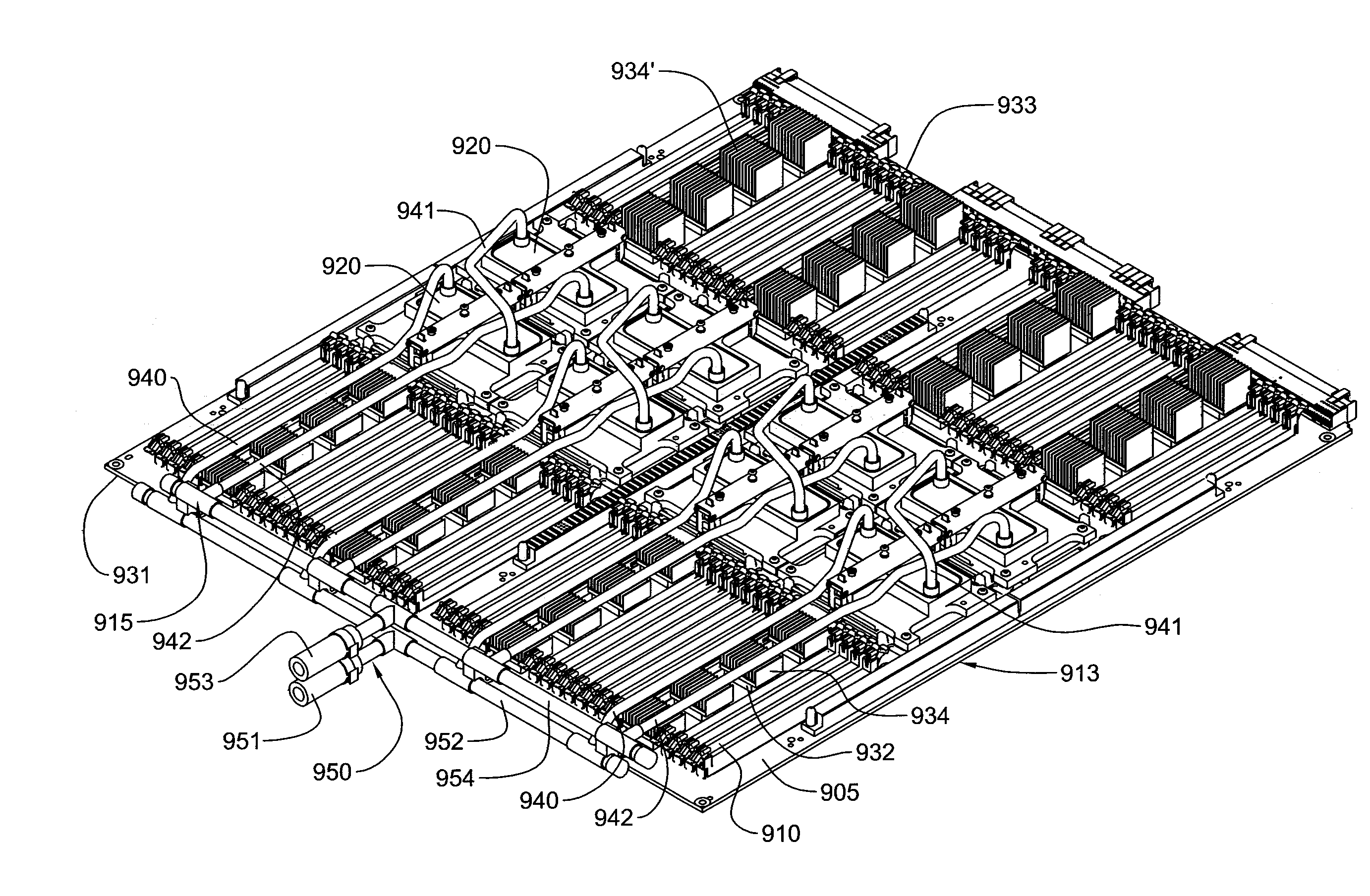
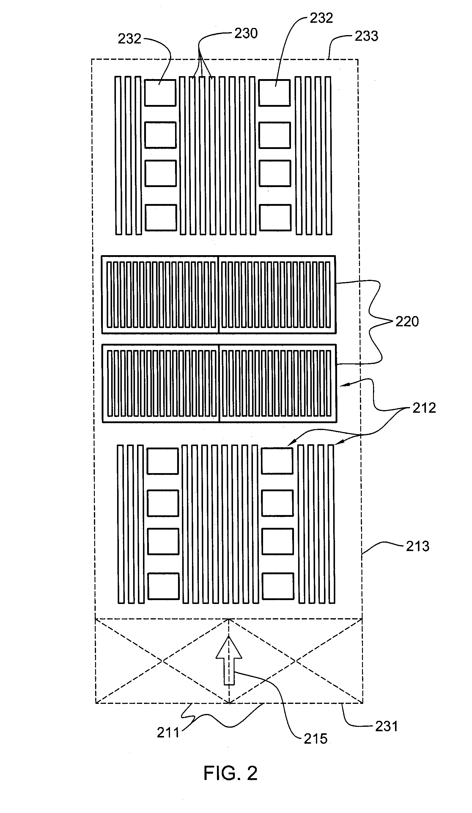
[0014]Briefly summarized, the present invention comprises in one aspect a method which includes: obtaining a coolant-carrying tube layout for interconnecting multiple liquid-cooled cold plates in series-fluid communication for cooling multiple heat-generating electronic components of an electronics system, the interconnected multiple liquid-cooled cold plates being a cooling subassembly, the multiple heat-generating electronic components to be plugged in fixed spaced relation into corresponding sockets on a supporting motherboard, and the coolant-carrying tube layout comprising at least one rigid coolant-carrying tube; determining for the coolant-carrying tube layout if stress in one or more rigid coolant-carrying tubes thereof exceeds a predetermined acceptable level, and determining if loss of actuation load on a heat-generating electronic component being cooled by the cooling subassembly exceeds an acceptable loss threshold, and if either is true, identifying at least one tube of the coolant-carrying tube layout having high stress, the at least one tube comprising at least one of a tube portion in torsion and a tube portion in bending when a force is applied to at least one liquid-cooled cold plate of the cooling subassembly, and reconfiguring the at least one tube having high stress to produce a reconfigured coolant-carrying tube layout and repeating the determining for the reconfigured coolant-carrying tube layout; performing analysis on the cooling subassembly and the multiple heat-generating electronic components of the electronics system once the coolant-carrying tube layout experiences tube stress below the defined acceptable level and a loss of actuation load on the multiple heat-generating electronic components below the acceptable loss threshold, the analysis including employing the available actuation load on at least part of the cooling subassembly and evaluating electrical connection loading between at least one heat-generating electronic component being cooled thereby and the supporting motherboard into which the heat-generating electronic components electrically connect in fixed spaced relation; and saving the coolant-carrying tube layout as a final design for interconnecting in series-fluid communication the multiple liquid-cooled cold plates of the cooling subassembly if the electrical connection loading is above an acceptable minimum level.
[0015]In a further aspect, a method of configuring a cooling subassembly for an electronics system is provided. This method includes: obtaining a coolant-carrying tube layout for interconnecting multiple liquid-cooled cold plates in series-fluid communication for cooling multiple h

Problems solved by technology

This trend poses a cooling challenge at both the module and system level.
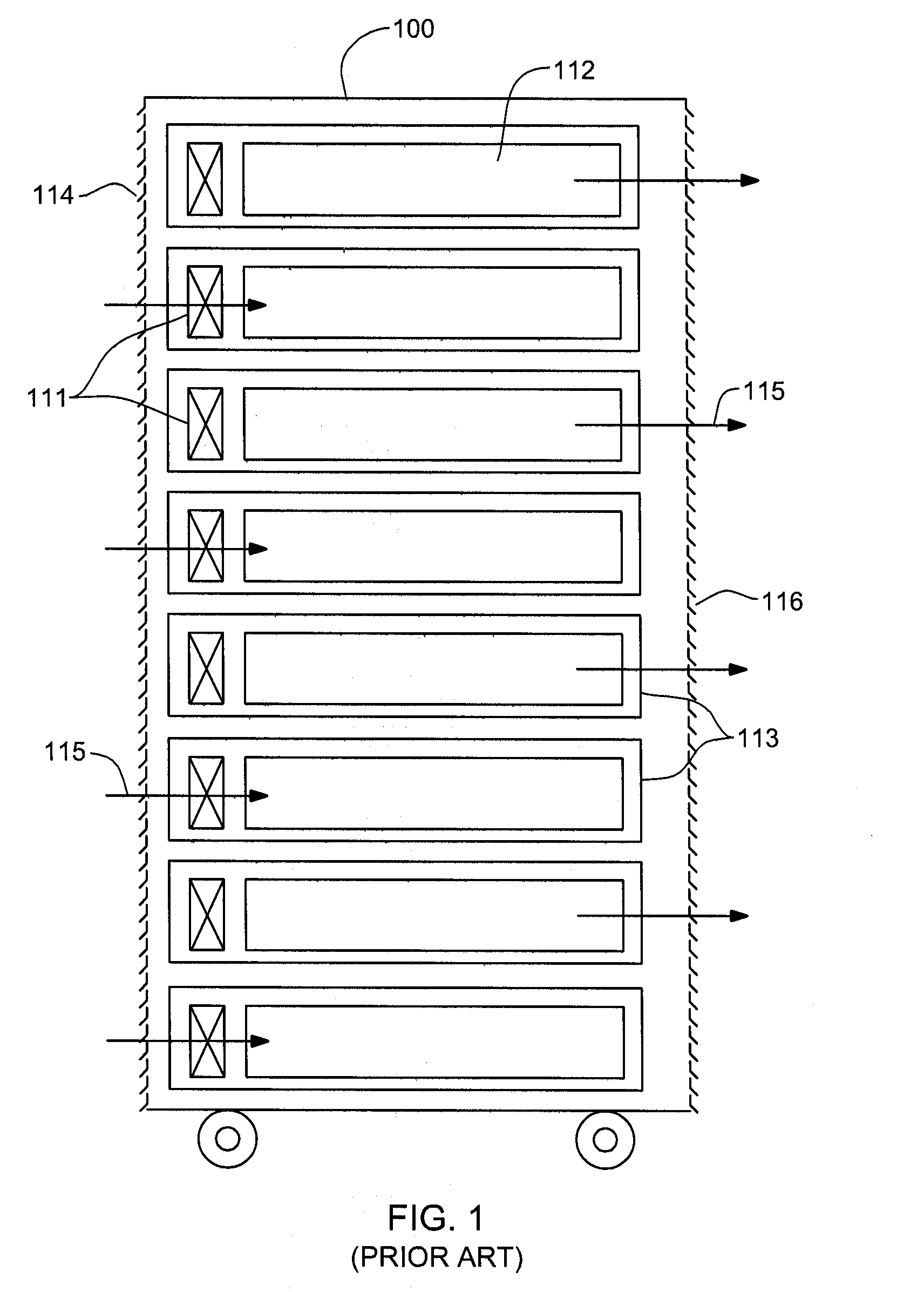
However, this approach is becoming unmanageable at the frame level in the context of a computer installation (e.g., data center).
The sensible heat load carried by the air exiting the frame will eventually exceed the ability of room air conditioning to effectively handle the load.
In such installations, not only will the room air conditioning be challenged, but the situation may also result in recirculation problems with some fraction of the “hot” air exiting one frame being drawn into the air inlet of the same or a nearby frame.
Furthermore, while the acoustic noise level o

Method used


Image

  • Methods for configuring tubing for interconnecting in-series multiple liquid-cooled cold plates
  • Methods for configuring tubing for interconnecting in-series multiple liquid-cooled cold plates
  • Methods for configuring tubing for interconnecting in-series multiple liquid-cooled cold plates

Examples


Embodiment Construction

[0044]As used herein “electronics system” comprises any system containing one or more heat generating components of a computer system or other electronics unit requiring cooling. The terms “electronics rack”, “electronics frame”, and “frame” are used interchangeably, and include any housing, rack, compartment, blade chassis, etc., having heat generating components of a computer system or electronics system and may be for example, a stand-alone computer processor having high, mid or low end processing capability. In one embodiment, an electronics frame comprises multiple electronics drawers, each having multiple heat generating components disposed therein requiring cooling. “Electronics drawer” refers to any sub-housing, blade, book, drawer, node, compartment, etc., having multiple heat generating electronic components disposed therein. Each electronics drawer of an electronics frame may be movable or fixed relative to the electronics frame, with rack mounted electronics drawers and ...


PUM


Abstract

Methods of configuring a cooling subassembly for an electronics system are provided, that is, for establishing a coolant-carrying tube layout for interconnecting multiple liquid-cooled cold plates in series-fluid communication for cooling multiple heat-generating electronic components of an electronics system. The electronic components are to be plugged in fixed relation into a preconfigured motherboard, and the tube layout includes at least one rigid coolant-carrying tube. Simplified analysis is initially performed to evaluate stress on the rigid tube(s) and determine if loss of actuation load on the electronic components exceeds an acceptable threshold, and if so, at least one tube having high stress is identified and reconfigured. Thereafter, analysis is performed to determine whether, with available actuation load on the cooling subassembly, electrical connection loading between the electronic components and the supporting motherboard is above an acceptable minimum level. If so, the coolant-carrying tube layout is chosen as a final design.

Description

CROSS-REFERENCE TO RELATED APPLICATIONS[0001]This application contains subject matter which is related to the subject matter of the following applications, each of which is assigned to the same assignee as this application and each of which is hereby incorporated herein by reference in its entirety:[0002]“Hybrid Cooling System and Method for a Multi-Component Electronics System”, Campbell et al., Ser. No. 11 / 539,902, filed Oct. 10, 2006;[0003]“Conductive Heat Transport Cooling System and Method for a Multi-Component Electronics System”, Campbell et al., Ser. No. 11 / 539,905, filed Oct. 10, 2006;[0004]“Method of Assembling a Cooling System for a Multi-Component Electronics System”, Campbell et al, Ser. No. 11 / 539,907, filed Oct. 10, 2006;[0005]“Liquid-Based Cooling System for Cooling a Multi-Component Electronics System”, Campbell et al., Ser. No. 11 / 539,910, filed Oct. 10, 2006;[0006]“Heatsink Apparatus for Applying a Specified Compressive Force to an Integrated Circuit Device”, Colb...

Claims


Application Information

Patent Timeline
IPC IPC(8): F25B7/00
CPCH05K7/20809G06F1/20
Inventor CAMPBELL, LEVI A.COLBERT, JOHN L.ELLSWORTH, MICHAEL J.SINHA, ARVIND K.
Owner IBM CORP
Why Eureka
Try Eureka