Redundant power supply architecture with voltage level range based load switching

a power supply and voltage level range technology, applied in the direction of dc source parallel operation, pulse technique, transportation and packaging, etc., can solve the problems of increasing reducing the inherent reliability and conversion efficiency of the regulated power supply, and general inefficiency of the linear regulator, so as to reduce the number of parts, reduce the cost and complexity of the power supply, and reduce the effect of thermal loss

Inactive Publication Date: 2008-07-10
SLT LOGIC
View PDF3 Cites 44 Cited by
  • Summary
  • Abstract
  • Description
  • Claims
  • Application Information

AI Technical Summary

Benefits of technology

[0023]An advantage of the one embodiment of the present invention is that the voltage level range based load switching architecture permits the use of a primary supply to source the low voltage loads, like the management power in the MicroTCA specification which is 3.3+/−10% Volts, while the second power supply is in the standby mode, where a diode-drop based redundancy fails to meet this feature.
[0024]An advantage of one embodiment of the present invention is that the voltage level range based load switching architecture permits the use o...

Problems solved by technology

This mode of control leads to substantial losses in the form of heat and therefore, the linear regulator is generally inefficient.
The resultant digital error voltage is then used to modulate the pulse width of the PWM.
In all of the above cases, the regulation methodologies require complex control circuitry which reduces the inherent reliability and conversion efficiency of the regulated power supply and also increases the cost and complexity of the power supply.
One of the problems associated with an active redundant configuration is that there is no mechanism to prevent current flow from the redundant power supply to the primary power supply should the primary power supply fail.
In effect, the ORing diode allows current to flow from the power supply to the load but presents a barrier to any current attempting to flow into the power supply from the load or the other power supplies connected to the load.
One of the other problems associated with an active redundant configuration is the ability to make one of the supplies to b...

Method used


Image

  • Redundant power supply architecture with voltage level range based load switching
  • Redundant power supply architecture with voltage level range based load switching
  • Redundant power supply architecture with voltage level range based load switching

Examples


Embodiment Construction

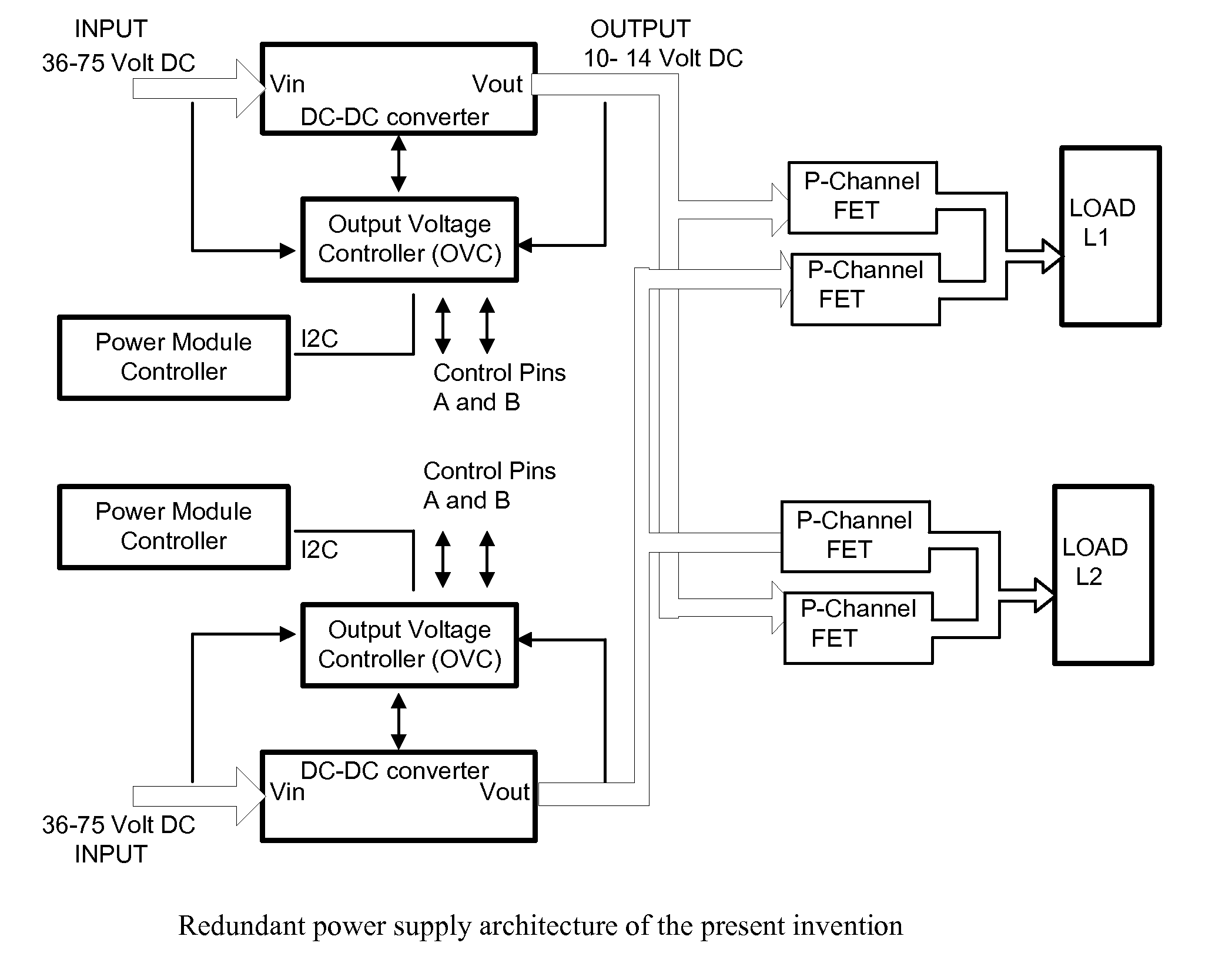
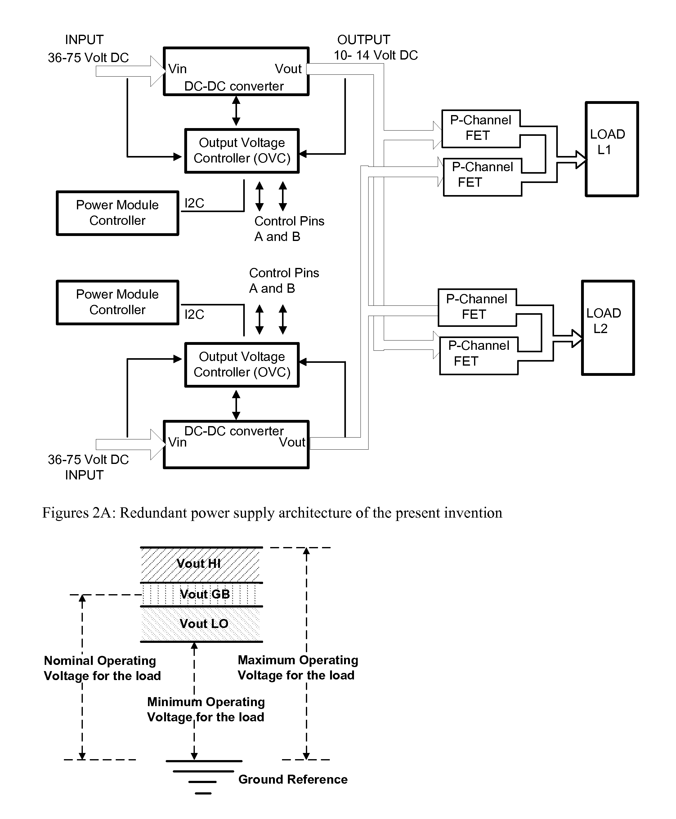
[0032]One embodiment of the present invention is schematically illustrated in the FIG. 2A. Power supplies A and B are isolated DC to DC converter. The power supplies A and B connected on the input side to a wide range input DC source of 36 Volts to 75 Volts. At the output side the Power supplies A and B are electrically coupled via a well known P Channel FETs to a load L1 and load L2, to provide redundancy and back up for loads L1 and load L2. The output of each power supply is FED back to the input side of each power supply to control PWM via a Output Voltage Controller (OVC). The Input of each power supply is also connected to each OVC. The controls of each OVC circuit are connected to the respective Power Module Controller. Discreet control pins A and B are provided for non controller based control of the OVC operation.

[0033]In regard to the present invention, the precise level of regulation of both of the power supplies is unimportant to provide active redundancy. What is import...


PUM


Abstract

A voltage level range based redundant power supply architecture is described wherein at least two power supplies are connected to an external load and maintained in an energized state. However, only one of the power supplies sources all the current requirements of the load while the other power supply remains in standby mode. This is achieved by manually or programmatically adjusting the voltage output of a first power supply and a second power supply connected in parallel to the external load such that the first power supply always outputs a higher potential difference at the point of load than the second power supply, thereby implementing a voltage level range of outputs of the power supplies so as to guarantee that all the current requirement of the load is sourced from the first power supply. The second power supply remains energized and upon failure of the first power supply instantaneously takes over the function of the failed power supply and powers the load.

Description

PRIORITY APPLICATION[0001]The present application claims priority to U.S. Provisional Application Ser. No. 60 / 883,444, filed Jan. 4, 2007, the disclosure of which is hereby incorporated by reference.FIELD OF THE INVENTION[0002]The present invention relates generally to the field of power supply architectures for powering high availability systems, and in particular to redundancy and fault tolerant power supply configurations.BACKGROUND OF THE INVENTION[0003]The Power Sources Manufacturers Association's (PSMA) Handbook of Standardized Terminology for the Power Sources Industry defines a power supply as a device for the conversion of available power of one set of characteristics to another set of characteristics to meet specified requirements. Power supplies are alternatively referred to as power converters. Typical applications of power supplies include conversion of ubiquitous Alternating Current (AC) power to a controlled or stabilized Direct Current (DC) for the operation of elect...

Claims


Application Information

Patent Timeline
IPC IPC(8): H02J1/10H02J3/38H02J7/34
CPCH02J1/10H03K17/76H03K17/06
Inventor SHARMA, VISWALENTZ, DAVID
Owner SLT LOGIC
Why Eureka
Try Eureka