
Imaging System

a technology of imaging system and image, applied in the field of imaging system, can solve the problems of radiation damage, skin and other tissue damage reddening, radiation dose reduction, etc., and achieve the effect of high image quality

Inactive Publication Date: 2008-07-10
SIEMENS HEALTHCARE GMBH
View PDF1 Cites 10 Cited by
  • Summary
  • Abstract
  • Description
  • Claims
  • Application Information

AI Technical Summary

Benefits of technology

[0008]When capturing an image sequence, non-damaging imaging may be achieved by taking individual images using a high radiation dose instead of continuously applying a high radiation dose to the patient. This provides high-resolution (i.e. highly detailed) images that can be used as the comparison basis for detecting a movement or change in the patient's body. Such an image is, for example, the reference image which is followed by at least one current image that was taken using a lower radiation dose. The radiation dose of the current image is set such that the image quality is adequate for comparison with the reference image. A computer may automatically compare the reference image with the current image. The computer may detect dynamic processes resulting in a change in the current image compared to the older reference image. Only if such a change is detected will another image, which will replace the reference image, be taken using a high radiation dose. The replacement reference image will provide the medical personnel with an updated high-quality visualization of the processes in the patient's body. The imaging method may be used with a flat-panel x-ray machine and / or a computed tomography (CT) scanner.
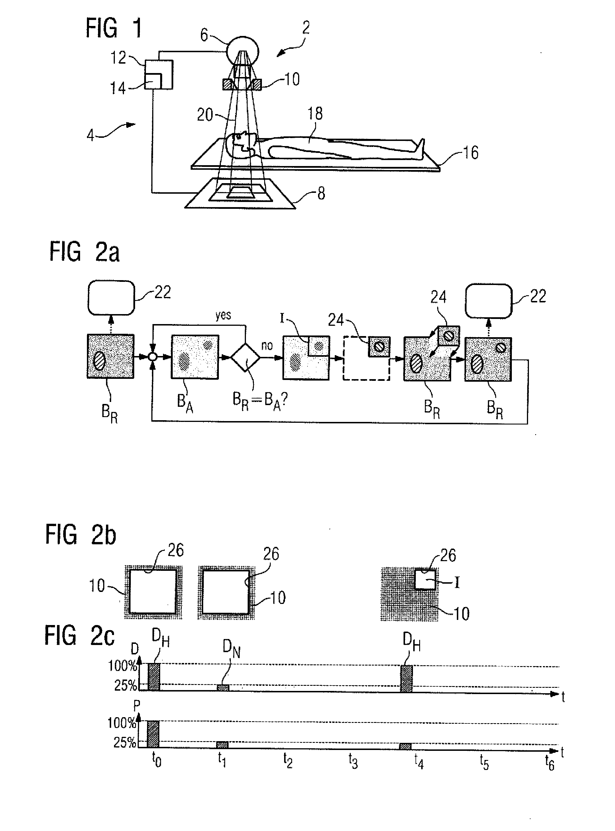
[0012]In one embodiment, to capture the image detail, a beam path of the medical imaging device is restricted by a collimator. The collimator may mask out part of the beam path, which reduces the radiation dose to which the patient is exposed. Using the part of the beam path passing through an aperture of the collimator, a high-quality recording of the region in which a change was detected in the current image can be obtained.
[0014]The collimator may be moved to a number of predetermined positions. The number of predetermined positions is correlated with the size of the collimator aperture. Image details may be captured from all the predetermined positions, so that the contiguously disposed image details cover the entire image. For example, four defined collimator positions are provided which are matched to the size of the collimator aperture. The collimator may be moved to one of the four positions, so that one quadrant of the reference image may be taken in each case. Establishing the predefined positions enables the collimator to be controlled in a particularly simple manner.
[0018]The current image may be taken with a radiation dose that may be less than 50% and, more preferably 25%, of the size of the radiation dose of the reference image. The radiation dose of the current image may be lower than the radiation dose of the reference image, however, it is sufficient for showing the relevant differences between the current image and the reference image in the specific application and using suitable methods. This may provide a particularly non-damaging patient imaging method in which the radiation dose for the patient is reduced.

Problems solved by technology

During lengthy treatments, such continuous exposure results in radiation damage, such as reddening of the skin and other tissue damage.
Alternatively, the radiation dose was reduced, even though this adversely affects the image quality of the x-ray images obtained, as the image sharpness depends on the radiation dose.
The radiation dose cannot therefore be reduced arbitrarily.

Method used


Image

  • Imaging System
  • Imaging System

Examples


Embodiment Construction

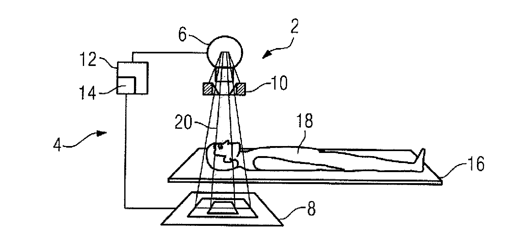
[0027]In one embodiment, as shown in FIG. 1, an imaging apparatus 2 includes an imaging device 4 with a radiation source 6, a radiation detector 8, and a collimator 10. The imaging device 4 may be an x-ray machine. The apparatus 2 may be controlled by a control unit 12 that includes a processing unit 14. A patient 18 positioned on a patient positioning table 16 may be moved into a beam path 20 emitted by a radiation source 6. A series of recordings of a region under examination of the patient 18 may be made using the imaging device 4. An image sequence may be recorded during a medical intervention with continuous irradiation of the patient 18.

[0028]A method for capturing an image sequence is shown in the block diagram of FIG. 2a. A reference image BR with high image sharpness is taken with a high radiation dose DH (see FIG. 2c). The reference image BR may be stored and / or displayed on a display 22. The display 22 provides the treating physician with visual assistance during the medi...


PUM

PropertyMeasurementUnit
imaging methodaaaaaaaaaa
thresholdaaaaaaaaaa
timeaaaaaaaaaa

Abstract

A medical imaging system is provided. The medical imaging system includes an imaging device with a radiation source and a detector, a control unit; and a processing unit. The processing unit is operable to compare a stored reference image taken using a high radiation dose with a current image taken using a lower radiation dose. The control unit is operable to trigger the imaging device to take a further image using a high radiation dose based on the comparison.

Description

[0001]The present patent document claims the benefit of the filing date of DE 10 2007 001 181.6, filed Jan. 5, 2007, which is hereby incorporated by reference.BACKGROUND[0002]The present embodiments relate to an imaging system for capturing an image sequence.[0003]During a number of medical applications (e.g. an endoscopic intervention), a patient is irradiated over a period of time for imaging purposes. The patient is continuously exposed to ionizing radiation during this time. During lengthy treatments, such continuous exposure results in radiation damage, such as reddening of the skin and other tissue damage. Medical personnel, such as the doctor carrying out the treatment and / or the medical personnel assisting the doctor may be in close proximity to the patient during the treatment, The medical personnel may be exposed to continuous stray radiation during the treatment.[0004]Conventially, exposing the patient and the medical personnel to radiation in this way was regarded as acc...

Claims


Application Information

Patent Timeline
Patent Type & Authority Applications(United States)
IPC IPC(8): G01N23/04
CPCA61B6/00A61B6/542A61B6/488
Inventor WEDEL, MATTHIAS
Owner SIEMENS HEALTHCARE GMBH
Learn More