
Electrode Wire For Solar Cell

a solar cell and electrode wire technology, applied in the direction of conductors, single bars/rods/wires/strips, conductors, etc., can solve the problem that the semiconductor substrate is unlikely to crack, and achieve excellent electrical conductivity

Active Publication Date: 2008-07-17
HITACHI METALS LTD
View PDF7 Cites 37 Cited by
  • Summary
  • Abstract
  • Description
  • Claims
  • Application Information

AI Technical Summary

Benefits of technology

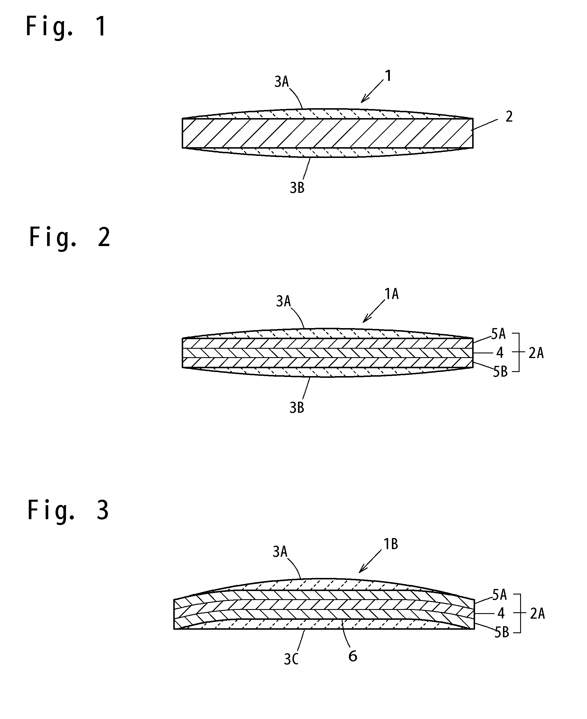
[0011]To overcome the problems described above, preferred embodiments of the present invention provide an electrode wire for a solar cell, which is usable as an alternative to the conventional clad electrode wire, which is less likely to cause cracks in a solar cell semiconductor substrate during soldering, and which has excellent electrical conductivity.

Problems solved by technology

Therefore, cracking is unlikely to occur in the semiconductor substrate.

Method used


Image

  • Electrode Wire For Solar Cell
  • Electrode Wire For Solar Cell
  • Electrode Wire For Solar Cell

Examples


example a

[0049]Various clad materials were prepared by press-bonding surface layers of oxygen-free copper (Cu: 99.97 mass %, O: 15 ppm) to opposite surfaces of an interlayer of aluminum (specified by JIS 1N90, Al: 99.90 mass %) or Invar (Fe-36.5 mass % Ni) and annealing the resulting stack for diffusion. The clad materials (core materials) each had a thickness of about 160 μm, and the ratio of the thickness of the interlayer to the thickness of the clad material is shown in Table 1. Each of the clad materials were slit to form elongated plates each having a width of about 2 mm, and each of the elongated plates were cut to a length of about 150 mm, whereby a plurality of core materials were prepared. The core materials were annealed at about 500° C. for about one minute for softening. Furthermore, a plurality of core materials were prepared in substantially the same manner as described above by using a rolled sheet of the oxygen-free copper, and some of the core materials were annealed for so...

example b

[0054]Various clad materials were each prepared by press-bonding surface layers of oxygen-free copper (Cu: 99.97 mass %, O: 15 ppm) to opposite surfaces of an interlayer of aluminum (specified by JIS 1N90, Al: 99.90 mass %) or Invar (Fe-36.5 mass % Ni) and annealing the resulting stack for diffusion. The clad materials (core materials) each had a thickness of about 200 μm, and the ratio of the thickness of the interlayer to the thickness of the clad material is shown in Table 2. The clad materials were annealed at about 500° C. for one minute for softening. Then, each of the clad materials were slit to form elongated plates each having a width of about 2 mm, and each of the elongated plates were cut to a length of about 150 mm, whereby a plurality of core materials were prepared. Furthermore, a plurality of core materials were prepared by annealing a rolled sheet of the oxygen-free copper for softening in the same manner as described above and then slitting the annealed sheet.

[0055]...


PUM


Abstract

A solar cell electrode wire includes a core material having a volume resistivity of not greater than about 2.3 μΩ·cm and a proof strength in the range of about 19.6 MPa to about 85 MPa, and a hot-dip solder plating layer disposed on a surface of the core material. The core material is preferably an annealed pure copper material having an oxygen content of not higher than about 20 ppm. The core material may be a clad material including an interlayer of aluminum and copper layers disposed on opposite surfaces of the interlayer.

Description

BACKGROUND OF THE INVENTION[0001]1. Field of the Invention[0002]The present invention relates to an electrode wire used as a connection lead wire for a solar cell.[0003]2. Description of the Related Art[0004]A solar cell includes a semiconductor substrate of a silicon semiconductor having PN junctions, and a connection lead wire soldered to a solder band provided across a plurality of linear front surface electrodes disposed on a front surface of the semiconductor substrate. A plurality of such solar cells are generally connected in series to provide a desired electromotive force. For the serial connection, one surface (a lower surface) of a connection lead wire is soldered to a front surface electrode of one solar cell, and the other surface (an upper surface) of the connection lead wire is soldered to a relatively large rear surface electrode of an adjacent solar cell.[0005]An electrode wire that is conventionally used as a material for the connection lead wire includes a core mat...

Claims


Application Information

Patent Timeline
IPC IPC(8): H01L31/0224H01B5/00B32B7/02H01B5/02
CPCH01L31/022425Y02E10/50H01L31/0512H01L31/0508H01L31/04H01L31/0224
Inventor SHIOMI, KAZUHIROISHIO, MASAAKIFUJITA, TOSHIAKI
Owner HITACHI METALS LTD
Learn More