Plasma Source with Liner for Reducing Metal Contamination

a technology of metal contamination and plasma source, which is applied in plasma technique, electrostatic charge, electric discharge tube, etc., can solve the problem of metal contamination of substrate doping

Inactive Publication Date: 2008-07-17
VARIAN SEMICON EQUIP ASSOC INC
View PDF37 Cites 29 Cited by
  • Summary
  • Abstract
  • Description
  • Claims
  • Application Information

AI Technical Summary

Problems solved by technology

The presence of the aluminum and the aluminum based materials can result in metal contaminating the substrate being doped.

Method used


Image

  • Plasma Source with Liner for Reducing Metal Contamination
  • Plasma Source with Liner for Reducing Metal Contamination
  • Plasma Source with Liner for Reducing Metal Contamination

Examples


Embodiment Construction

[0009]While the present teachings are described in conjunction with various embodiments and examples, it is not intended that the present teachings be limited to such embodiments. On the contrary, the present teachings encompass various alternatives, modifications and equivalents, as will be appreciated by those of skill in the art.

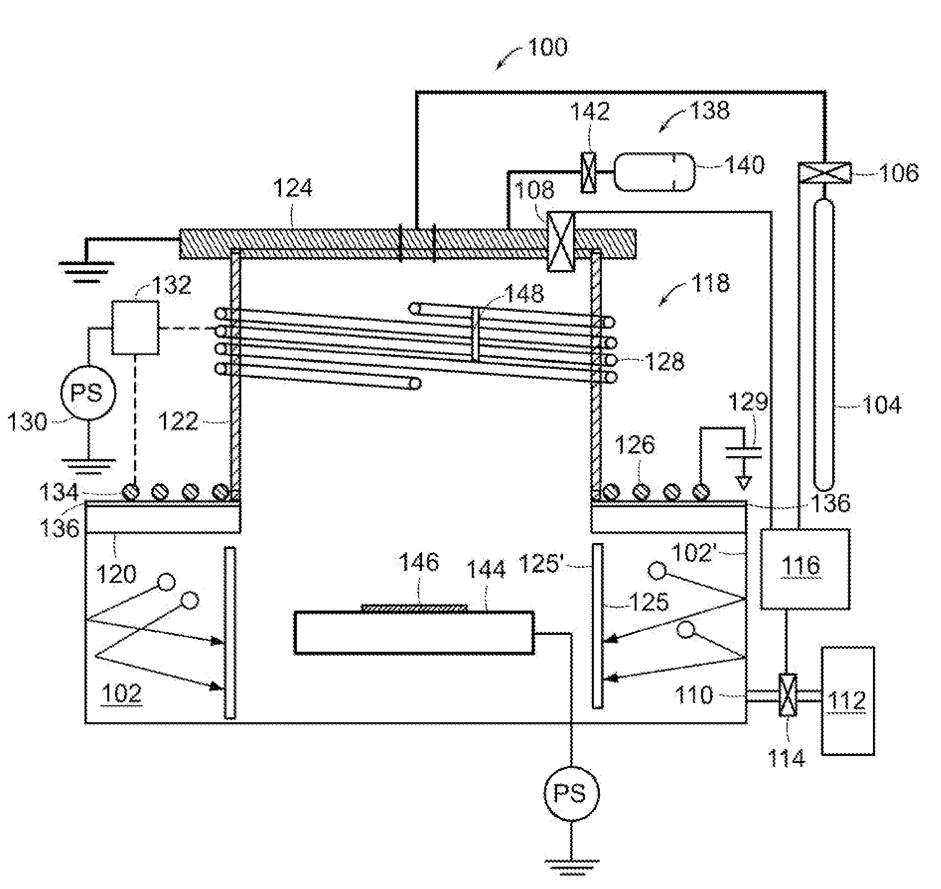
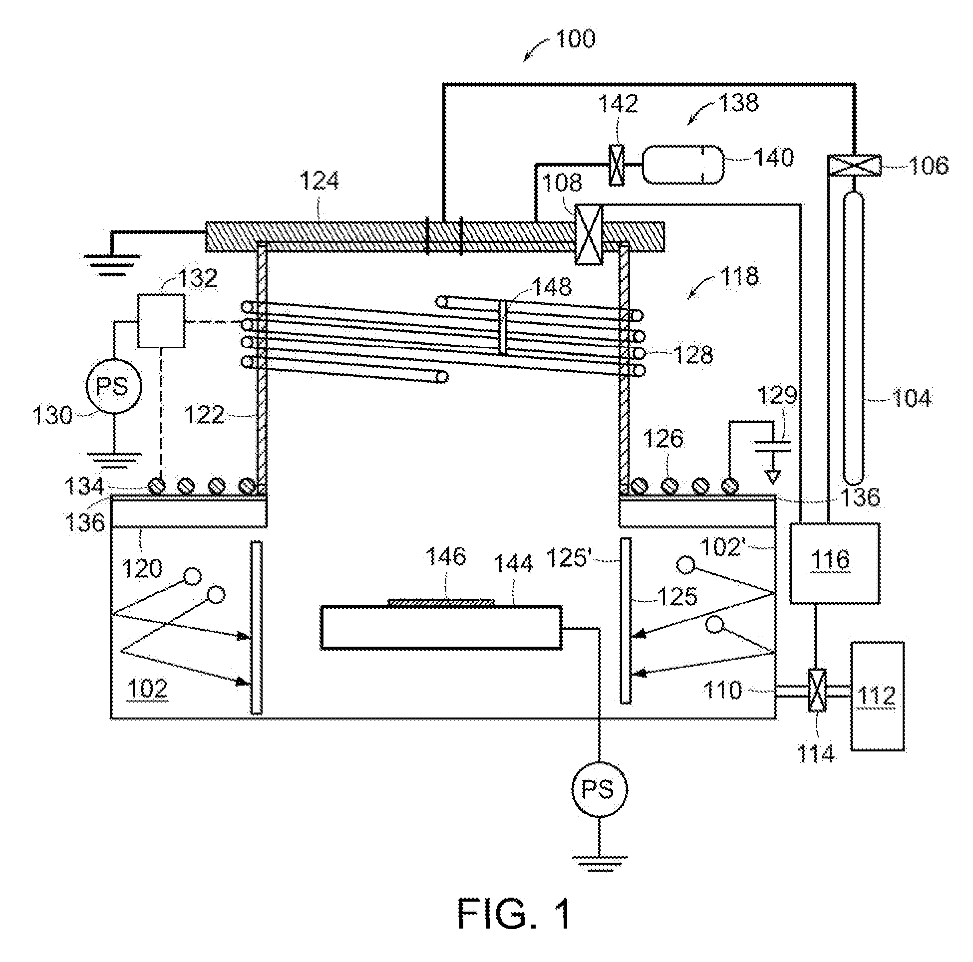
[0010]For example, although the plasma chamber liners of the present invention are described in connection with reducing metal contamination in plasma doping apparatus, the plasma chamber liners of the present invention can be used to reduce metal contamination in many types of processing apparatus including, but not limited to, various types of etching and deposition systems.

[0011]It should be understood that the individual steps of the methods of the present invention may be performed in any order and / or simultaneously as long as the invention remains operable. Furthermore, it should be understood that the apparatus of the present invention can include ...


PUM


Abstract

A plasma source having a plasma chamber with metal chamber walls contains a process gas. A dielectric window passes a RF signal into the plasma chamber. The RF signal excites and ionizes the process gas, thereby forming a plasma in the plasma chamber. A plasma chamber liner that is positioned inside the plasma chamber provides line-of-site shielding of the inside of the plasma chamber from metal sputtered by ions striking the metal walls of the plasma chamber.

Description

[0001]The section headings used herein are for organizational purposes only and should not to be construed as limiting the subject matter described in the present application.BACKGROUND OF THE INVENTION[0002]Conventional beam-line ion implanters accelerate ions with an electric field. The accelerated ions are filtered according to their mass-to-charge ratio to select the desired ions for implantation. Recently plasma doping systems have been developed to meet the doping requirements of some modern electronic and optical devices. Plasma doping is sometimes referred to as PLAD or plasma immersion ion implantation (PIII). These plasma doping systems immerse the target in a plasma containing dopant ions and bias the target with a series of negative voltage pulses. The electric field within the plasma sheath accelerates ions toward the target which implants the ions into the target surface.[0003]Plasma doping systems typically include plasma chambers that are made of aluminum because alu...

Claims


Application Information

Patent Timeline
Patent Type & Authority Applications(United States)
IPC IPC(8): H05F3/00
CPCH01J37/32412H01J37/32495H01J37/32633
Inventor HERTEL, RICHARD J.LI, YOU CHIAMCGRAIL, PHILIP J.MILLER, TIMOTHY J.PERSING, HAROLD M.SINGH, VIKRAM
Owner VARIAN SEMICON EQUIP ASSOC INC
Why Eureka
Try Eureka