Particle removal apparatus and method and plasma processing apparatus

a technology of plasma processing apparatus and particle removal, which is applied in the field of particle removal apparatus and method and plasma processing apparatus, can solve the problems of plasma disturbance, reduced production yield or deterioration of the operating rate of the processing apparatus, and inability to remove electrically neutral or negatively charged particles

Active Publication Date: 2005-02-24
TOKYO ELECTRON LTD
View PDF5 Cites 26 Cited by
  • Summary
  • Abstract
  • Description
  • Claims
  • Application Information

AI Technical Summary

Benefits of technology

[0011] The present invention is contrived to solve the aforementioned problems. It is, therefore, an object of the present invention to provide a method of removing particles ...

Problems solved by technology

These particles generated within the chamber are attached to a surface of the substrate to be processed, thereby causing a reduction in a production yield or deterioration of operating rate of the processing apparatus.
However, in the aforementioned prior art, the electrically neutral or negatively charged particles cannot be removed basically.
However, if a jig 214 of a metal member is disposed inside the chamber of the plasma processing apparatus, particularly, in the vicinity of the plasma generation region, a plasma is disturbed, whereby controlling a plasma distribution characteristic becomes difficult.
Still further, there is a problem that the metal member may cause a metal contamination.
Therefore, it is difficult to apply such...

Method used


Image

  • Particle removal apparatus and method and plasma processing apparatus
  • Particle removal apparatus and method and plasma processing apparatus
  • Particle removal apparatus and method and plasma processing apparatus

Examples


second embodiment

[0070] (Second Embodiment)

[0071]FIG. 9 shows a configuration of a plasma etching apparatus having a particle removal apparatus in accordance with a second preferred embodiment of the present invention. In the drawing, like reference numerals will be assigned to like parts having substantially same configurations or functions, and redundant description thereof will be omitted in the specification and the accompanying drawings. Here, a characteristic feature of the second preferred embodiment will be discussed mainly. In the second preferred embodiment, a member for performing a drift transfer on a positively charged particle in a particle charging region 76, same as in the aforementioned first embodiment, is included, so that a particle can be discharged outside the chamber further efficiently.

[0072] As shown in FIG. 9, a first charging electrode 102 embedded in a film-shaped insulator 100 is installed in an inner wall of the ceiling of a chamber 10 containing the inner wall surface...

third embodiment

[0076] (Third Embodiment)

[0077]FIG. 11 shows a configuration of a plasma etching apparatus having a particle removal apparatus in accordance with a third preferred embodiment of the present invention. In the drawing, the same reference numerals with those of the first and the second embodiment (FIGS. 1 and 9) will be assigned to like parts having substantially same configurations or functions, and redundant description thereof will be omitted in the specification and the accompanying drawings. Here, a characteristic feature of the third preferred embodiment will be discussed mainly. In the third embodiment, means or a method for more forcibly transferring or delivering the particles charged positively in a particle charging region 76 is included, so that the particles can be discharged outside a chamber 10 more efficiently, as compared with the second embodiment.

[0078] As shown in FIG. 11, an upper charging electrode 102 is divided into a central charging electrode 102A and a perip...

fourth embodiment

[0085] (Fourth Embodiment)

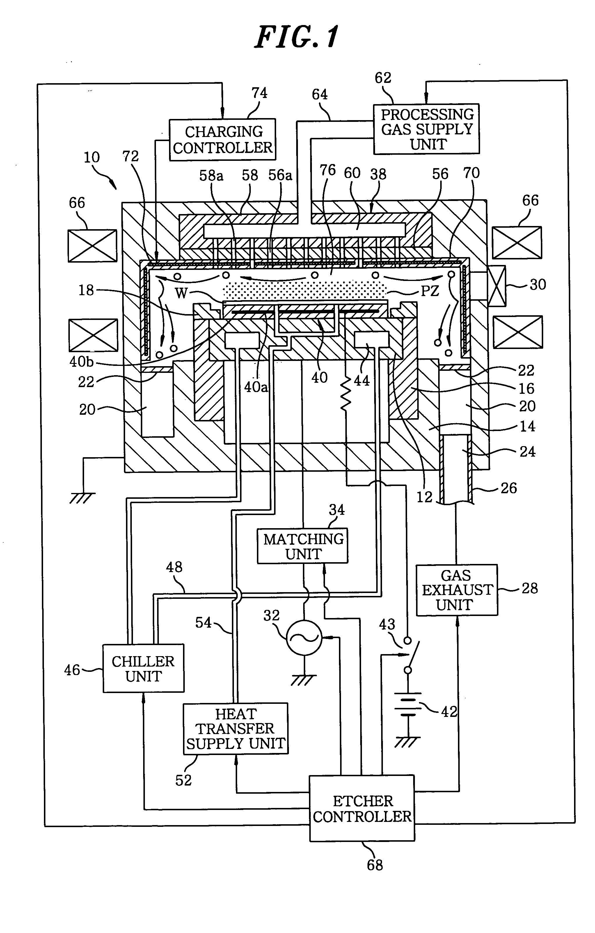
[0086]FIG. 13 shows a configuration of an apparatus in accordance with a fourth embodiment. The fourth embodiment is same as the third one, except that two characteristic features are added. The first characteristic feature is that a DC positive voltage is applied to a substrate W side (e.g., the electrode 40a of an electrostatic chuck 40) to thereby repel a positively charged particle therefrom in order to prevent the falling of the positively charge particle onto a substrate W to be processed. For this, a variable output voltage DC power source 114 is electrically connected to an electrostatic chuck electrode 40a on a susceptor 12, via a low-pass filter 116. Here, the low-pass filter 116 functions to cut off a high frequency from a high frequency power source 32.

[0087] A second characteristic feature is that the particle removing is facilitated by applying a negative voltage to a baffle plate 22 disposed in an opening of a gas exhaust path 20 in a bottom...


PUM

PropertyMeasurementUnit
Magnetic fieldaaaaaaaaaa
Electrical conductanceaaaaaaaaaa
Electric potential / voltageaaaaaaaaaa

Abstract

A particle removal apparatus for removing particles from a chamber of a plasma processing apparatus, wherein the chamber is connected to a gas exhaust port and a plasma of a processing gas is generated in the chamber to plasma process a substrate to be processed, includes a particle charging control member for positively charging particles generated within the chamber by positive ions of an ion sheath region formed in a region other than the vicinity of the substrate to be processed, wherein positively charged particles are discharged from the chamber via the gas exhaust port. Therefore, there is no plasma disturbance or metal contamination, and thus can be applied to a practical use.

Description

FIELD OF THE INVENTION [0001] The present invention relates to a technology of removing particles in a processing apparatus for performing a film forming processing or a microprocessing; and more particularly, to a method and apparatus of removing particles generated within a plasma processing apparatus. BACKGROUND OF THE INVENTION [0002] In a fabrication of a semiconductor device or a liquid crystal display, or the like, a substrate to be processed such as a semiconductor substrate, a glass substrate, or the like, is loaded into a processing vessel or a chamber of a processing device, and a film forming processing (chemical vapor deposition, etc.) or a microprocessing of a film (dry etching, etc.) is performed in an airtight or a depressurized chamber, wherein undesired particles are bound to be generated within the chamber. The production of these particles can be caused by the peeling off of reaction products that have been deposited within an inner wall of the chamber, or by gro...

Claims


Application Information

Patent Timeline
IPC IPC(8): H05H1/46B23K9/00C23C16/44C25F1/00C25F3/30H01J37/32H01L21/00H01L21/205H01L21/304H01L21/3065
CPCC23C16/4401H01J2237/022H01J37/32431
Inventor MORIYA, TSUYOSHINAGAIKE, HIROSHI
Owner TOKYO ELECTRON LTD
Why Eureka
Try Eureka