Electron beam lithography method and apparatus using a dynamically controlled photocathode

a technology of dynamic control and electron beam, which is applied in the field of electron beam lithography method and apparatus using a dynamic control photocathode, can solve the problems of long path length, inconvenient use, and very time-consuming process

Active Publication Date: 2008-07-17
KLA TENCOR TECH CORP
View PDF6 Cites 15 Cited by
  • Summary
  • Abstract
  • Description
  • Claims
  • Application Information

AI Technical Summary

Problems solved by technology

However, it is disadvantageous in that the process is very time-consuming, due to the sequential, point-wise writing.
Unfortunately, such magnetic prisms force electron beams along electron paths that can be of on the order of a meter or more in length.
Such long path lengths are capable of seriously degrading the electron beam 102 and are not desirable.

Method used


Image

  • Electron beam lithography method and apparatus using a dynamically controlled photocathode
  • Electron beam lithography method and apparatus using a dynamically controlled photocathode
  • Electron beam lithography method and apparatus using a dynamically controlled photocathode

Examples


Embodiment Construction

[0026]The present invention has been particularly shown and described with respect to certain embodiments and specific features thereof. The embodiments set forth hereinbelow are to be taken as illustrative rather than limiting. It should be readily apparent to those of ordinary skill in the art that various changes and modifications in form and detail may be made without departing from the spirit and scope of the invention.

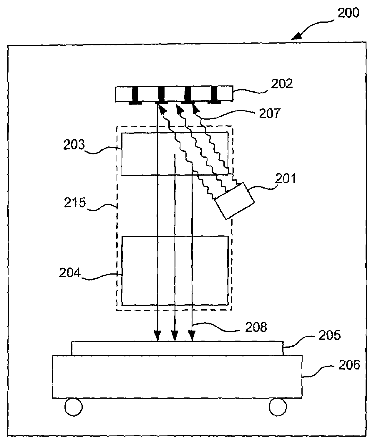
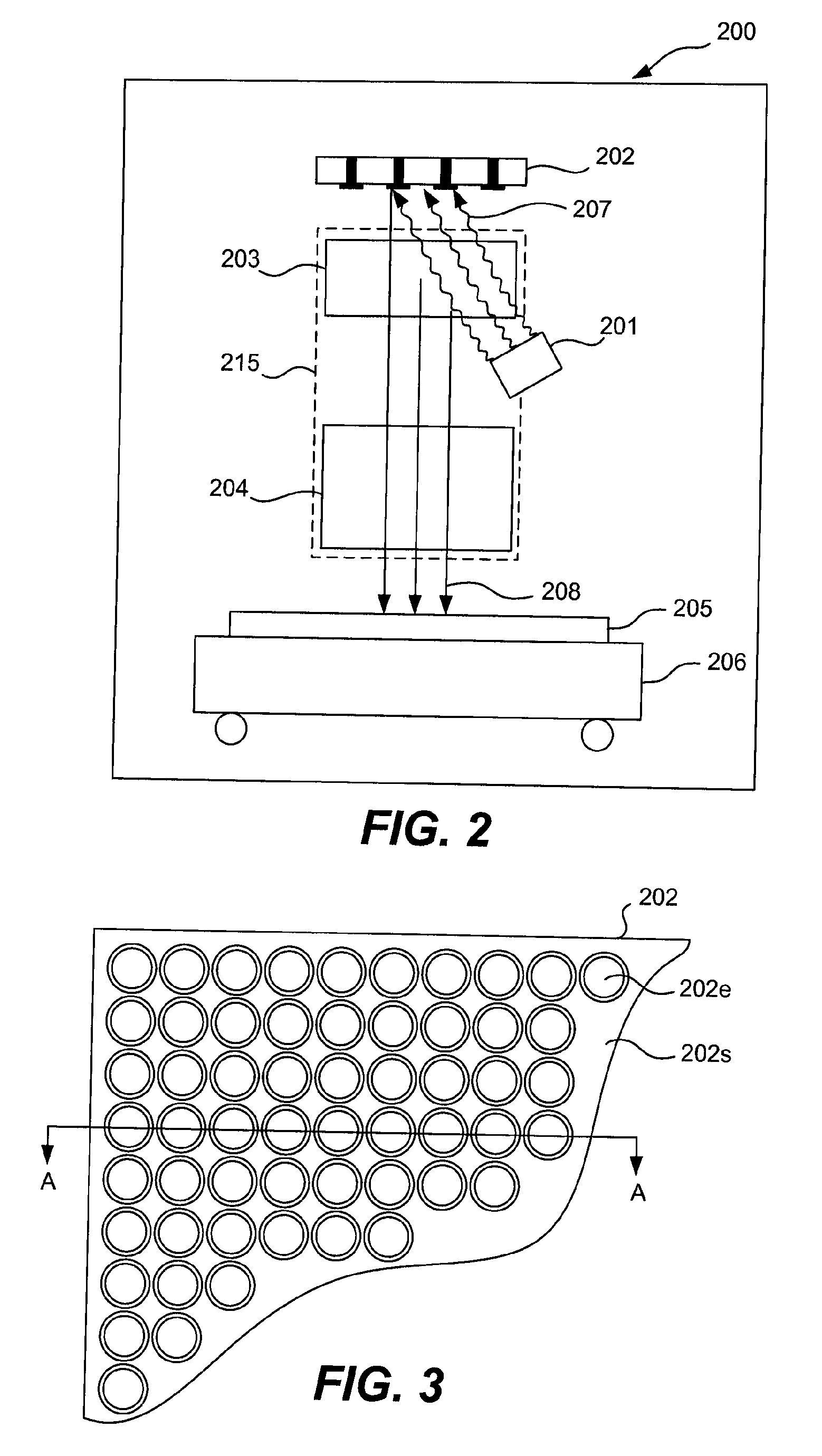
[0027]In general, the present invention encompasses maskless electron beam projection lithography apparatus and methods for their use in generating patterned targets which can include, but are not limited to, semiconductor wafers and masks, as well as other surfaces capable of pattern transfer with an electron beam.

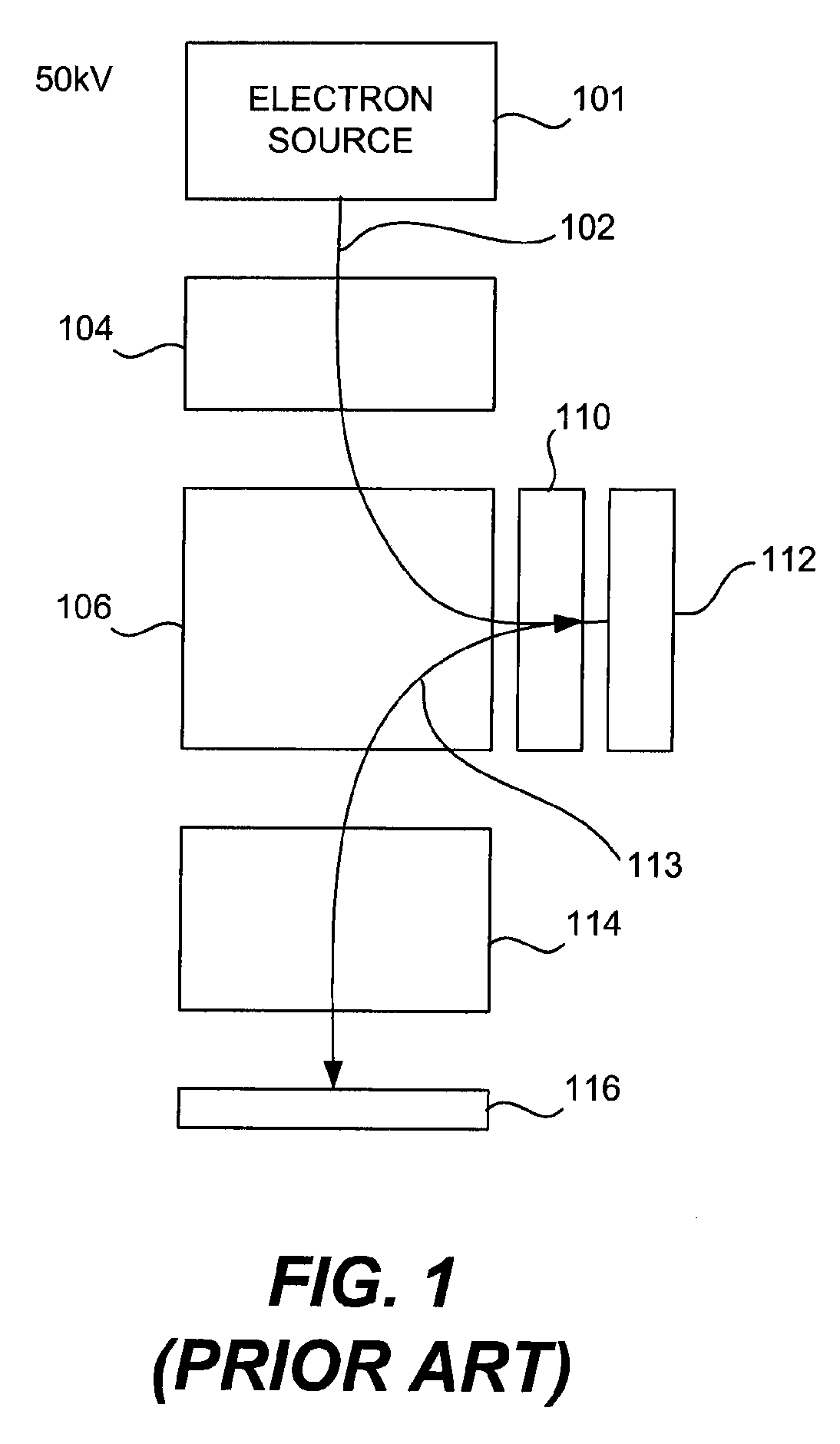
[0028]As discussed above, electron-beam direct write (REBL) lithography has the potential to achieve excellent resolution and a reasonable throughput. However, certain limitations are present in the known implementations of that technology. First is th...


PUM


Abstract

Embodiments of the invention include an electron beam lithography device using a dynamically controllable photocathode capable of producing a patterned electron beam. One such implementation includes a dynamic pattern generator configurable to produce an electron beam having a desired image pattern impressed thereon. Such an electron beam pattern being enabled by selectively activating programmable photoemissive elements of the pattern generator. The apparatus further including an illumination source arranged to direct a light beam onto the dynamic pattern generator to produce the electron beam having the desired pattern. The electron beam being directed through associated electron optics configured to receive the electron beam from the dynamic pattern generator and direct the electron beam onto a target substrate mounted on a stage.

Description

CROSS REFERENCE TO RELATED PATENT APPLICATION[0001]This application is related to, and claims priority from, Application No. 60 / 884,595 (Attorney Docket No. KLA1P174P / P1880), entitled “Electron Beam Lithography Method and Apparatus Using a Dynamically Controlled Photocathode”, by Allen M. Carroll, filed Jan. 11, 2007, which is herein incorporated by reference in its entirety.TECHNICAL FIELD[0002]The invention described herein relates generally to methods and apparatus for projecting a patterned electron beam onto a target substrate. The patterned electron beam enables the transfer of a selected pattern to a surface of a target substrate. Particularly, the invention refers to embodiments wherein the patterned electron beam is generated by an illuminated dynamically controlled pattern generator having an array of addressable and selectively actuatable electron emitting elements formed thereon.BACKGROUND[0003]As is well-understood in the art, a lithographic process includes the pattern...

Claims


Application Information

Patent Timeline
Patent Type & Authority Applications(United States)
IPC IPC(8): G21K5/04
CPCB82Y10/00B82Y40/00H01J1/34H01J2237/31779H01J37/3174H01J2237/06333H01J37/073
Inventor CARROLL, ALLEN M.
Owner KLA TENCOR TECH CORP
Why Eureka
Try Eureka