
Management of tracking models

a tracking model and model technology, applied in direction finders using radio waves, measurement devices, instruments, etc., can solve problems such as miscorrelation, difficulty, and sensor itself cannot provide any indication of report origin, and achieve intelligent and significant reduction of potential track hypotheses.

Inactive Publication Date: 2008-07-17
L 3 COMMUNICATIONS ASA LIMITED +1
View PDF11 Cites 26 Cited by
  • Summary
  • Abstract
  • Description
  • Claims
  • Application Information

AI Technical Summary

Benefits of technology

[0004]By associating multiple sensor reports with a single logical track deemed to represent a target, it is possible to deduce parameters such as object velocity as well as position, and to better decide which sensor reports should be incorporated into the estimation of which track. Commonly, this is achieved with a data processing technique using Kalman filters (“New Results in Linear Filtering and Prediction Theory”, Kalman R. E. and Bucy, R. S., Trans ASME, Journal of Basic Engineering, March 1961) implemented in software on suitable dedicated or general purpose computer hardware.
[0005]Kalman filters provide an efficient and recursive way to estimate the state variables of a process, in a way that continually seeks to minimise the error between the estimated state variables and the underlying trajectory. To improve tracking methods, assumptions about the process dynamics are built into the track estimation process. For the tracking of civil aircraft, a limited number of different descriptions of the possible process dynamics may be suitable, for example describing level flight, climbing / descending, and turning. Level flight dynamics may assume a fixed velocity in a straight line, requiring only position and velocity state variables, while climbing / descending dynamics may assume a constant rate of change of altitude. For military scenarios, different dynamics may be suitable for describing different types of ballistic and non-ballistic missile trajectories, helicopter dynamics and the wider range of possible aircraft dynamics.
[0008]An alternative approach is to use multiple models which do not interact significantly, if at all. Such arrangements may be referred to as Autonomous Multiple Models (AMMs). The use of autonomous multiple models overcomes particular problems such as how to combine multiple models with different numbers of state variables, reduces computational overheads accrued in the model interaction process, and can result in a tracking process which responds more quickly to changes in track dynamics. Although interacting multiple models have been more extensively discussed, a recent publication relating to autonomous models is A. T. Alouani and J. E. Gray, Proc SPIE Acquisition, Tracking and Pointing XVII, Vol. 5082, 2003.
[0015]Within this context, the invention provides a number of rules which enable a tracking system to discriminate between miscorrelation and manoeuvre, by comparing sets of models at current and prior times and, where necessary, across track processes, to effect an intelligent and significant reduction in potential track hypotheses.

Problems solved by technology

However, difficulties may arise if, even after the gating process, it is not clear to which of several possible tracks a sensor report should be allocated, or if the sensor report should be used to start a new track.
In the majority of cases the sensor itself cannot provide any indication of report origin.
Where a sensor report is used to update the wrong track, or a spurious sensor report is used to update a track, a miscorrelation has occurred.

Method used


Image

  • Management of tracking models
  • Management of tracking models
  • Management of tracking models

Examples


first embodiment

Detailed Process

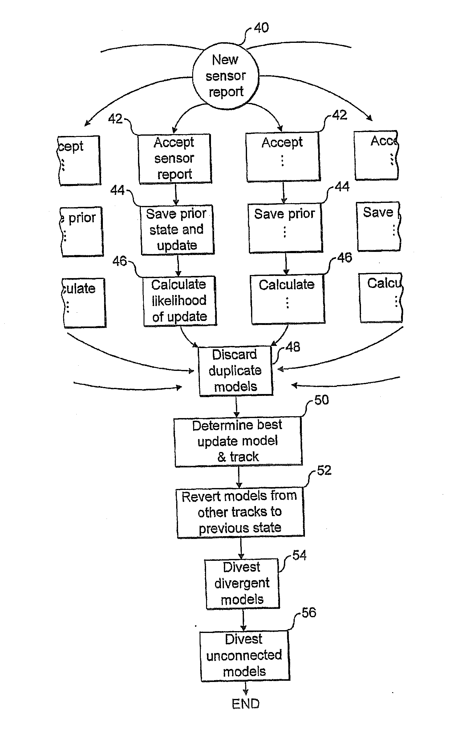
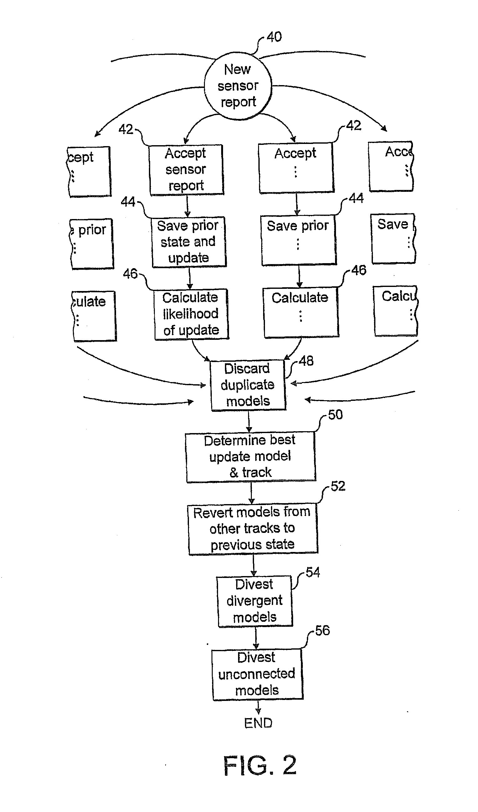
[0044]FIG. 2 is a flow diagram illustrating the processing carried out in respect of a new sensor report 40. Sensor reports may be used both to initiate new tracks and to update existing track models. Only the update process will be considered in detail here.

[0045]Each sensor report is sent to all of the models 14. Each sensor report is processed independently and completely before proceeding to the next one. Each model applies a gating process at step 42 to decide whether or not to update using the sensor report, using techniques familiar in the field of tracking using Kalman filters. Any model that accepts a sensor report creates a copy of its prior state as a separate model process and updates using the sensor report, at step 44.

[0046]Each model that updates using the new sensor report calculates, at step 46, a likelihood of the update based on a weighted distance measure and the model residual covariance matrix.

[0047]The set of models which has updated is further...

second embodiment

Detailed Process

[0056]Each incoming sensor measurement is processed independently and completely before proceeding to the next one. Each sensor report also undergoes whatever coordinate conversions may be necessary, removal of known biases and so on. The detailed sequence of process steps is illustrated in FIGS. 5 and 6.[0057]1. Each new sensor report is sent to all tracking processes, 72, 74, 76 each of which in turn sends the data to its constituent models 78.[0058]2. For each model 78, a gating process 92 is applied to the sensor report. The result will be an accept (the model will update using the sensor report) or reject (the sensor data is inapplicable).[0059]3. Any model that accepts a sensor report calculates 94 a likelihood, defined in equation (1) below. It also creates 96 an updated model state from the current model state combined with the accepted sensor report using techniques familiar in the field of tracking. The current model state is retained unchanged (also step 9...


PUM


Abstract

The present invention relates to methods and apparatus for tracking moving objects, such as ballistic missiles and aircraft, on the basis of discrete sensor measurements, such as radar reports and reports from optical sensors. In particular, but not exclusively, the invention is useful for the simultaneous tracking of multiple, fast moving, closely spaced objects, such as deploying ballistic missiles and raids of fast agile aircraft, in which the track dynamics of each object are modelled using a collection of autonomous, i.e. non-interacting, multiple dynamics models. Embodiments of the invention were particularly developed to be effective in tracking ballistic missiles using early warning radar, and similarly demanding and complex battle scenarios.

Description

CROSS REFERENCE TO RELATED APPLICATIONS[0001]This patent application claims priority to International Application PCT / GB2006 / 000827 filed on Mar. 8, 2006 which claims priority to GB application no. 0504889.7 filed Mar. 8, 2005, entitled, “MANAGEMENT OF TRACKING MODELS”, the contents and teachings of which are hereby incorporated by reference in their entirety.[0002]The present invention relates to methods and apparatus for tracking moving objects, such as ballistic missiles and aircraft, on the basis of discrete sensor measurements, such as radar reports and reports from optical sensors. In particular, but not exclusively, the invention is useful for the simultaneous tracking of multiple, fast moving, closely spaced objects, such as deploying ballistic missiles and raids of fast agile aircraft, in which the track dynamics of each object are modelled using a collection of autonomous, i.e. non-interacting, multiple dynamics models. Embodiments of the invention were particularly develo...

Claims


Application Information

Patent Timeline
Patent Type & Authority Applications(United States)
IPC IPC(8): G01S13/72G01S3/72G01S7/00
CPCG01S13/726G01S7/003
Inventor EASTHOPE, PAULSMITH, KEVINWAGGETT, TIM
Owner L 3 COMMUNICATIONS ASA LIMITED
Learn More