Optical element, aberration correcting element, light converging element, objective optical system, optical pickup device, and optical information recording reproducing device

a technology of aberration correction and optical elements, applied in the field of optical elements, can solve the problems of increasing numerical aperture, inadequate recording/reproducing characteristic, increasing cost, etc., and achieve the effect of reducing coma aberration

Inactive Publication Date: 2008-07-17
KONICA MINOLTA OPTO
View PDF6 Cites 5 Cited by
  • Summary
  • Abstract
  • Description
  • Claims
  • Application Information

AI Technical Summary

Benefits of technology

[0034]a coma aberration correcting element provided between the objective lens and a light source to emit a light flux which enters in not parallel to the optical axis into the objective optical system and to reduce a coma aberration generated when the objective optical system is driven in the direction perpendicular to the optical axis by the driving device;

Problems solved by technology

A method is considered by which the optical parts for the high density optical disk and the optical system for DVD or CD are selectively switched corresponding to the recording density of the optical disk for which the information is recorded / reproduced, as a method by which the information is appropriately recorded / reproduced while keeping the interchangeability also for any one of the high density optical disk and DVD, further, CD, however, because a plurality of optical systems are necessary, it is disadvantageous for size-reduction, further, the cost is increased.
Problems proper to the high density optical disk are (1) the chromatic aberration accompanied by a reduction of wavelength of the laser optical source (2) the spherical aberration change accompanied by an increase of numerical aperture.
This wavelength change is about several nm, however, because the wavelength dispersion is large in the blue violet wavelength area, while the objective optical system is focused again, it is in the de-focus condition, and the adequate recording / reproducing characteristic is not obtained.
Further, (2) is a problem actualized for the reason that the spherical aberration generated in the objective optical system is increased in proportion to fourth power of the numerical aperture.
In the objective optical system of high numerical aperture, because the spherical aberration when the wavelength of the incident light flux is changed, is increased, the allowance for the wavelength of the laser light source becomes severe.
Particularly, because there is an influence of the wavelength dispersion in the blue violet wavelength area, this problem is more actualized.
Further, in order to reduce a production cost, it is effective that the objective optical system is formed of a plastic lens, however, because the spherical aberration generated due to the refractive index change accompanied by the temperature change is increased, when the temperature in the optical pickup device is changed, the recording / reproducing characteristic of the information for the high density optical disk is interfered.

Method used


Image

  • Optical element, aberration correcting element, light converging element, objective optical system, optical pickup device, and optical information recording reproducing device
  • Optical element, aberration correcting element, light converging element, objective optical system, optical pickup device, and optical information recording reproducing device
  • Optical element, aberration correcting element, light converging element, objective optical system, optical pickup device, and optical information recording reproducing device

Examples


first embodiment

The First Embodiment

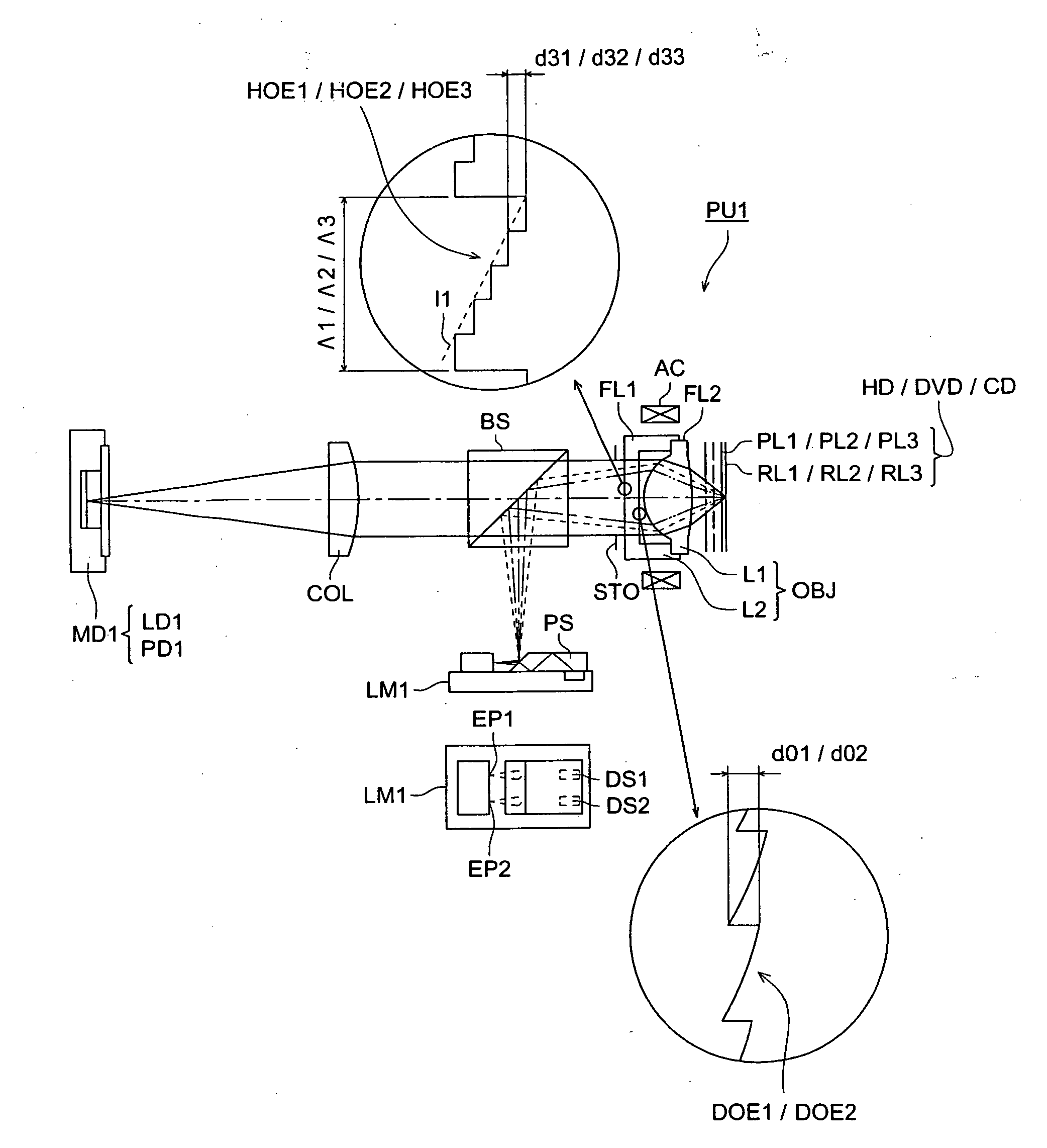
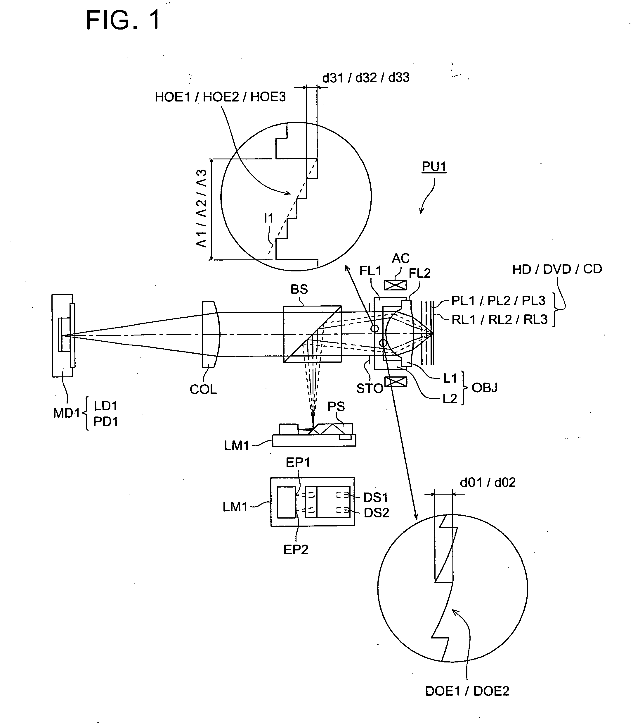
[0612]FIG. 1 is a view generally showing the structure of the first optical pickup device PU1 by which the recording / reproducing of the information can be adequately conducted also for any one of the high density optical disk HD, DVD, and CD. The optical specification of the high density optical disk HD is, the wavelength λ1=408 nm, thickness t1 of protective layer PL1=0.0875 mm, numerical aperture NA1=0.85, the optical specification of DVD is, the wavelength λ2=685 nm, thickness t2 of protective layer PL2=0.6 mm, numerical aperture NA2=0.60, and the optical specification of CD is, the wavelength λ3=785 nm, thickness t3 of protective layer PL3=1.2 mm, and numerical aperture NA3=0.45. However, a combination of the wavelength, thickness of the protective layer, and numerical aperture, is not limited to this.

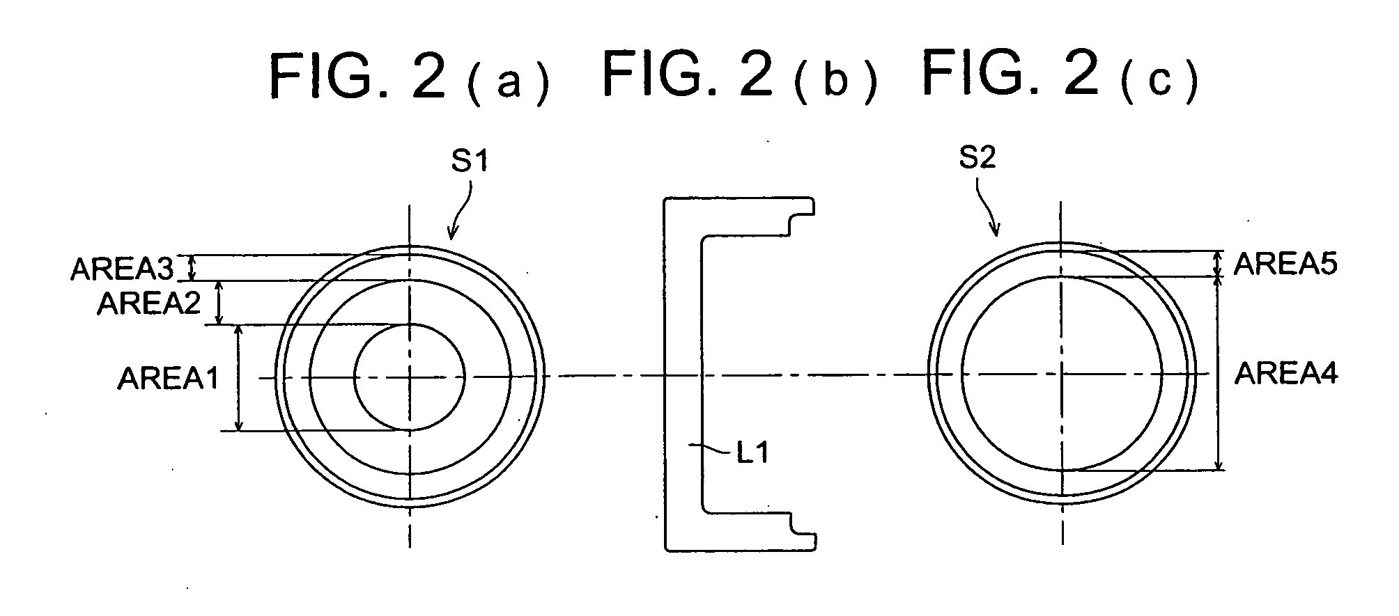
[0613]The optical pickup device PU1 is structured by: an objective optical system OBJ structured by: a module MD1 for the high density optical disk HD in which ...

second embodiment

The Second Embodiment

[0644]FIG. 3 is a view generally showing a structure of the second optical pickup device PU2 by which the recording / reproducing of the information can be adequately conducted for any one of the high density optical disk HD, DVD and CD. The optical specification of the high density optical disk is the wavelength λ1=408 nm, the thickness t1 of the protective layer PL1=0.0875 mm, numerical aperture NA1=0.85, the optical specification of DVD is the wavelength λ2=658 nm, the thickness t2 of the protective layer PL2=0.6 mm, numerical aperture NA2=0.67, and the optical specification of CD is the wavelength λ3=785 nm, the thickness t3 of the protective layer PL3=1.2 mm, numerical aperture NA3=0.45. However, a combination of the wavelength, thickness of the protective layer, and numerical aperture is not limited to this.

[0645]The optical pickup device PU2 is structured by: a laser module LM2 for the high density optical disk HD / DVD structured by the first light emitting ...

third embodiment

The Third Embodiment

[0678]FIG. 5 is a view generally showing a structure of the third optical pickup device PU3 by which the recording / reproducing of the information can be adequately conducted for any one of the high density optical disk, DVD and CD. The optical specification of the high density optical disk is the wavelength λ1=408 nm, the thickness t1 of the protective layer PL1=0.0875 mm, numerical aperture NA1=0.85, the optical specification of DVD is the wavelength λ2=658 nm, the thickness t2 of the protective layer PL2=0.6 mm, numerical aperture NA2=0.67, and the optical specification of CD is the wavelength λ3=785 nm, the thickness t3 of the protective layer PL3=1.2 mm, numerical aperture NA3=0.51. However, a combination of the wavelength, thickness of the protective layer, and numerical aperture is not limited to this.

[0679]The optical pickup device PU3 is structured by: a laser module LM1 for DVD / CD structured by the module MD1 for high density optical disk HD in which the...


PUM

PropertyMeasurementUnit
refractive indexaaaaaaaaaa
wavelength λ1aaaaaaaaaa
wavelengthaaaaaaaaaa

Abstract

An optical system for use in an optical pickup apparatus comprises a first optical surface having a superposition type diffractive structure including a plurality of ring-shaped zones which are formed concentrically around an optical axis, wherein each ring-shaped zone is composed of a plurality of stepped sections stepwise, and a second optical surface having a diffractive structure including a plurality of ring-shaped zones which are formed concentrically around an optical axis, wherein each of the plurality of ring-shaped zones are divided by a stepped section to generate a diffractive light ray of diffractive order whose absolute value is not small than 1 for the light flux.

Description

BACKGROUND OF THE INVENTION[0001]The present invention relates to an optical element for an optical pickup device, aberration correcting element, light converging element, objective optical system, optical pickup device using these optical elements, and optical information recording reproducing device.[0002]Recently, in the optical pickup device, a tendency to reduce the wavelength of a laser light source used as the light source for recording the information into an optical disk, is advanced, for example, a laser light source of a wavelength 405 nm such as a blue violet semiconductor laser or a blue violet SHG laser in which the wavelength conversion of the infrared semiconductor laser is conducted by using the second harmonics generation, is being put to practical use.[0003]When these blue violet laser light sources are used, in the case where an objective lens whose numerical aperture (NA) is the same as that of DVD (digital versatile disk) is used, the information of 15-20 GB ca...

Claims


Application Information

Patent Timeline
Patent Type & Authority Applications(United States)
IPC IPC(8): G11B7/00G02B13/00G02B5/18G02B13/16G02B13/18G11B7/125G11B7/1275G11B7/1353G11B7/1369G11B7/1372G11B7/1374G11B7/1376G11B7/1378G11B7/1392
CPCG11B7/1275G11B7/1353G11B7/1369G11B7/1374G11B2007/13727G11B7/1378G11B7/13922G11B7/13925G11B2007/0006G11B7/1376
Inventor KIMURA, TOHRUYAMASHITA, KIYOSHIMORI, NOBUYOSHIATARASHI, YUICHI
Owner KONICA MINOLTA OPTO
Why Eureka
Try Eureka