Optical receptacle, optical sub assembly and optical transceiver

a technology of optical sub-assembly and optical transceiver, which is applied in the direction of optics, instruments, optical light guides, etc., can solve the problems of large impact, large impact, and coupling loss, and achieve the effect of avoiding large impact, simple structure and reducing characteristic variation

Inactive Publication Date: 2008-07-17
FUJITSU LTD
View PDF5 Cites 17 Cited by
  • Summary
  • Abstract
  • Description
  • Claims
  • Application Information

AI Technical Summary

Benefits of technology

[0036]The present invention has been developed in consideration of the above-mentioned problems, and it is therefore an object of the invention to provide an optical receptacle with a simple structure, which avoids the occurrence of a large impact by preventing a plug body from coming into collision with an optical propagation member such as a fiber stub or a glass plate due to a force of an elastic body of a terminal member at the insertion of the terminal member while reducing a characteristic variation at the application of a load to a cord.
[0048]Thus, as an advantage, the present invention can provide an optical receptacle with a simple structure, which avoids the occurrence of a large impact due to the collision of a plug body with an optical propagation member by a force of an elastic body of an optical connector plug at the insertion of the optical connector plug while reducing a characteristic variation at the application of a load to a cord.

Problems solved by technology

In such a situation, a coupling loss occurs, and in the case of the TOSA, the optical output fluctuates.
However, the inventor of the subject application found that the precision sleeve 142 has the following problems.
At this time, there is a problem in that a large impact exceeding, for example, 10,000 G occurs since the ferrules 106 and 122 made of a hard material such as zirconia come into collision with each other.
Such a large impact leads to that the fiber stub 108 inserted under pressure settles down or the performance of precise electronic parts mounted in the interior of the package 104 suffers degradation.
No employment of the spring 123 makes it difficult to bring the plug ferrule 122 into contact with the fiber stub 108 or the glass plate 116, which leads to the occurrences of reflection and coupling loss.
That is, there is also a problem which arises with the techniques disclosed in the aforesaid Patent Documents 1 and 2 in that the characteristic variation increases at the application of a load to a cord.
In fact, in a case in which a TOSA employing the optical receptacle 150 with the above-mentioned structure shown in FIG. 22 was mounted in an SFP and an LC optical fiber cord was connected thereto, when a predetermined load (for example, 100 gf) was applied to the cord and the optical output fluctuation of the TOSA was confirmed, a large fluctuation occurred, so it was of no practical use.
However, since this structure has a limit in the enlargement of the opening portion, difficulty is encountered in sufficiently eliminating the above-mentioned catching at the insertion of the optical connector plug.
Still moreover, in a case in which the slit is formed up to an intermediate position in the longitudinal direction, the repeated insertion / extraction of the plug ferrule constituting the optical connector plug causes the stress to concentrate on the cut portion forming this slit, so it is considered that cracks starting at this cut portion can occur, which creates a problem in that the lifetime of the optical receptacle becomes shorter.

Method used


Image

  • Optical receptacle, optical sub assembly and optical transceiver
  • Optical receptacle, optical sub assembly and optical transceiver
  • Optical receptacle, optical sub assembly and optical transceiver

Examples


first embodiment

[a] Description of First Embodiment of the Present Invention

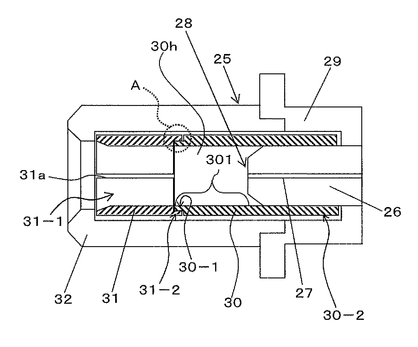
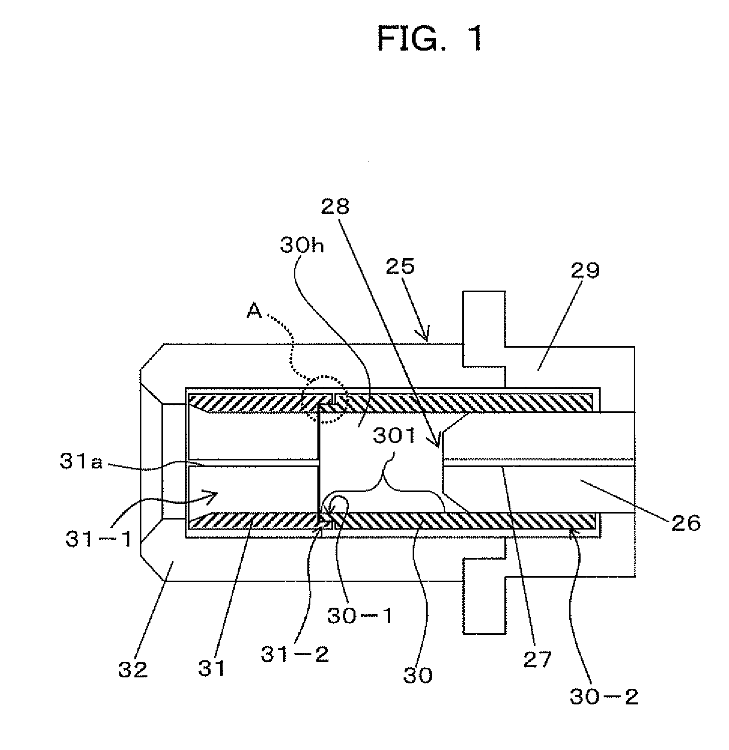
[0072]FIG. 1 is a cross-sectional view showing an optical receptacle 25 according to a first embodiment of the present invention.

[0073]The optical receptacle 25 according to the first embodiment is applicable as an optical receptacle for an LC connector for use in a TOSA and ROSA to be mounted in a pluggable type optical transceiver module such as an SFP or XFP. That is, the optical receptacle 25 can accept an terminal member such as the above-mentioned optical connector plug 130 shown in FIG. 16 for optical coupling.

[0074]The optical receptacle 25 according to the first embodiment includes a fiber stub 28, a holder 29 made of a metal, a precision sleeve (solid sleeve) 30, a slit sleeve 31 and a sleeve case 32.

[0075]The fiber stub 28 is an optical propagation member fixedly fitted in an opposite side (other end portion 30-2 side) to the insertion side (one end portion 30-1 side) of a plug body such as a plug ferrule 122 whi...


PUM


Abstract

The present invention relates to an optical receptacle which avoids the occurrence of a large impact at the insertion of the terminal member. The optical receptacle comprises a tubular slit sleeve in which a split is made in an axial direction and into which the plug body is introduced from its first end portion, a tubular solid sleeve into which the plug body introduced is inserted from its one end portion and which has an inner diameter which makes substantially no gap with respect to an outer diameter of the plug body, and an optical propagation member which is secured to the other end portion of the solid sleeve and which is optically coupled to the plug body, with a second end portion opposite to the first end portion of the slit sleeve and the one end portion of the solid sleeve being engaged to be connected to each other.

Description

BACKGROUND OF THE INVENTION[0001]1) Field of the Invention[0002]The present invention relates to an optical receptacle, optical sub assembly and optical transceiver suitable for use in TOSA (Transmitter Optical Sub Assembly) or ROSA (Receiver Optical Sub Assembly) to be mounted in a pluggable type optical transceiver module such as SFP (Small Form-Factor Pluggable) or XFP (10 Gigabit Small Form-Factor Pluggable).[0003]2) Description of the Related Art[0004]In recent years, along with the establishment of the MSA (Multi Source Agreement) for a pluggable type optical transceiver module such as SFP or XFP, it has come into widespread use in optical communication systems based upon SONET / SDH (Synchronous Optical NETwork / Synchronous Digital Hierarchy) and Ethernet (registered trademark). In this pluggable type optical transceiver module, optical assemblies with transmission and reception functions, such as TOSA (Transmitter Optical Sub Assembly) and ROSA (Receiver Optical Sub Assembly), ...

Claims


Application Information

Patent Timeline
Patent Type & Authority Applications(United States)
IPC IPC(8): G02B6/36
CPCG02B6/3825G02B6/3846G02B6/4292G02B6/4246G02B6/3874
Inventor MITAMURA, NOBUAKI
Owner FUJITSU LTD
Why Eureka
Try Eureka