Device for smoothing the surfaces of hard or soft materials

a technology of hard or soft materials and surfaces, applied in the direction of gear teeth manufacturing tools, gear-teeth manufacturing apparatus, file, etc., can solve the problems of increasing the cost of replacing pads, so as to achieve fewer clogging problems

Inactive Publication Date: 2008-07-17
GELFUSO RUSSELL
View PDF15 Cites 6 Cited by
  • Summary
  • Abstract
  • Description
  • Claims
  • Application Information

AI Technical Summary

Benefits of technology

[0022]In operation, the user would secure the disc cutting plate to a random orbital sander. He or she would start the sander and place it on the work piece. As the cutting blades are simultaneously rotated and orbited, the user would feel a slight pull from one direction to another as the cutting blades pass. As previously described, while cutting blades on one side of the disc cutting plate are shearing material, cutting blades on the opposite side are smoothing material. And since the disc cutting plate is a har

Problems solved by technology

A problem faced by such workers is the cost associated with constantly replacing sand paper.
These costs can mount both in the expense of the pads and in the time required to replace.
The replacement time can be considerable, as workers often must traverse ladders and locate fresh pads.
Moreover, as traditional abrading devices wear, they provide variable finish, which is not desirable.
However, the grit level immediately begins to degrade when the pad use begins.
When smoothing soft material surfaces or low melting point surfaces, the sheet back side 33 becomes easily clogged with waste or amorphous material that can not be removed, resulting in premature failure and replacement.
When smoothing hard material surfaces the sheet back side 33 often breaks down and loses the ability to remove material from the material surface resulting in premature failure and replacement.
When smoothing soft and hard material surfaces simultaneously, i.e. a nail in a piece of wood, the flexible sheet 30 often tears also resulting in premature failure and replacement.
Although this advance addresses the issues of premature failure experienced with the coated flexible shee

Method used


Image

  • Device for smoothing the surfaces of hard or soft materials
  • Device for smoothing the surfaces of hard or soft materials
  • Device for smoothing the surfaces of hard or soft materials

Examples


second embodiment

[0059]Referring now to FIG. 5, the present invention is shown. A finishing plate can be formed as a mouse cutting plate 16. The mouse cutting plate 16 is manufactured with the same tooth profile as shown in FIG. 3a-e. Rather than manufacturing a round plate, the mouse cutting plate 16 has a corner profile which enables use in corners where disc cutting plate 1 could not reach. The hook attachment 14 is attached to the platen of a handheld orbital sander 13. The loop attachment 15 is attached to the mouse cutting plate 16. The hook attachment 14 and the loop attachment 15 together are also known as Velcro.

third embodiment

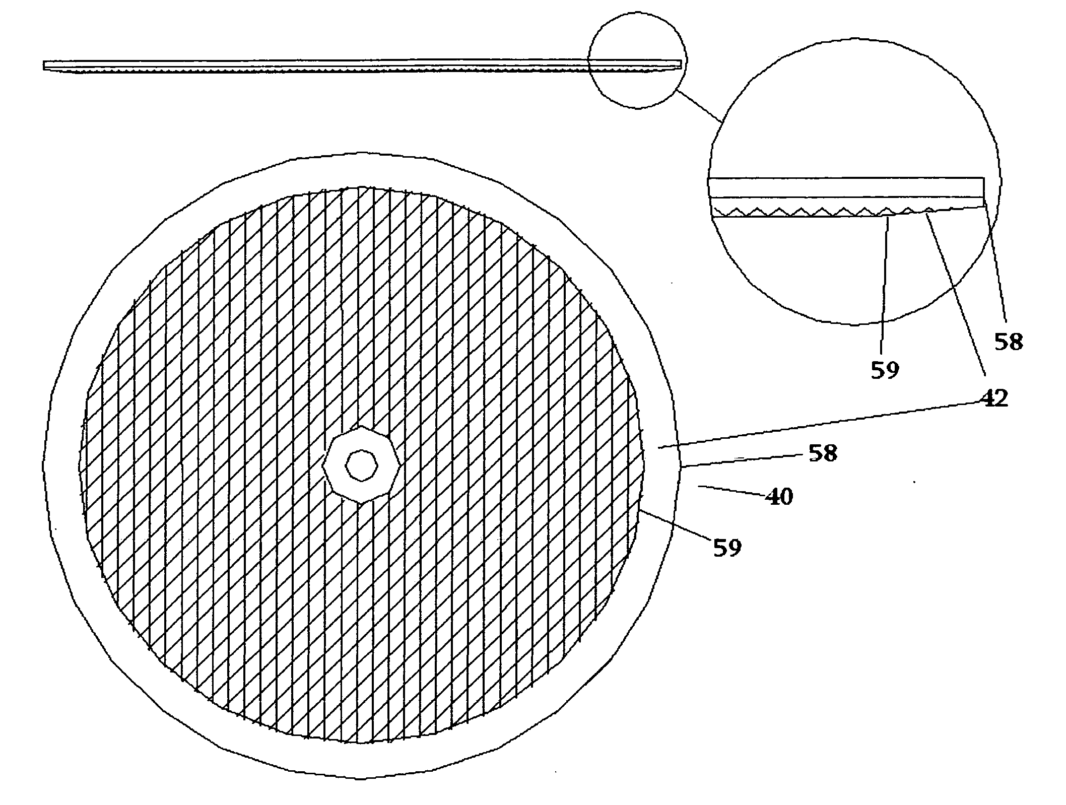
[0060]Referring now to FIG. 6, the present invention is shown. A finishing plate can be formed as a second disc cutting plate 40, which is substantially similar to the disc cutting plate 1. A disc plate thru-hole 41 is added to the center of the second disc cutting plate 40. A shaft mounting screw 20 is then inserted through the disc plate thru-hole 41, and into stub shaft adapter 19. The stub shaft adapter 19 is then tightened into the drill chuck 43 of a handheld power drill 18. The present invention can then be used for various additional surfacing finishing operations including those where the user has only the handheld power drill 18 available.

[0061]Referring now to FIG. 7, the disc cutting plate 1 or the second disc cutting plate 40 can have an outer periphery chamfer 42 added around the entire outer edge. As seen, the cutting blade 2 will gradually be removed from an inner chamfer ring 59 to an outer disc edge 58.

[0062]With the outer periphery chamfer 42, the disc cutting pla...


PUM

PropertyMeasurementUnit
Angleaaaaaaaaaa
Angleaaaaaaaaaa
Angleaaaaaaaaaa

Abstract

The present invention is a finishing plate and method of fabricating a finishing plate. The finishing plate can be fabricated to various shapes, and can be used with various surfacing machines. In a preferred mode, the present invention is a disc cutting plate which can be used with a random orbital sander, and can be used to replace traditional abrasive sheets such as sandpaper. The present invention can be used in smoothing various materials including wood, painted wood, plastic, and various metals.

Description

CROSS-REFERENCE TO RELATED APPLICATIONS[0001]The present application claims the benefit of U.S. Provisional Application No. 60 / 880,725, filed Jan. 17, 2007.SEQUENCE LISTING[0002]Not ApplicableSTATEMENT REGARDING FEDERALLY SPONSORED RESEARCH OR DEVELOPMENT[0003]Not ApplicableTHE NAMES OF THE PARTIES TO A JOINT RESEARCH AGREEMENT[0004]Not ApplicableINCORPORATION-BY-REFERENCE OF MATERIAL SUBMITTED ON A COMPACT DISC[0005]Not ApplicableBACKGROUND OF THE INVENTION[0006]1. Field of the Invention[0007]Various means are available for mechanically smoothing the surfaces of materials. Rotary, vibratory, belt and orbital sanders, have various sanding surface shapes and sizes, and are often used for this purpose. The invention is described in terms of its application to random orbital sanders, rotary sanders, and orbital sanders. However, application to any surfacing machine is included in the field of the invention.[0008]2. Description of Related Art[0009]In the field of surface finishing, work...

Claims


Application Information

Patent Timeline
IPC IPC(8): B24B7/00B24B1/00
CPCB23D67/06B23D67/12B23D71/005Y10T407/1815B23D73/00Y10T29/4561B23D71/02
Inventor GELFUSO, RUSSELL
Owner GELFUSO RUSSELL
Why Eureka
Try Eureka