System and related circuits and methods for detecting and locating illicit cellular telephone use within a facility

a technology of illicit cellular phone use and system, applied in the direction of electrical equipment, wireless commuication services, security arrangements, etc., can solve the problems of unauthorized disclosure of classified data, financial information, medical records, etc., and achieve the effect of accurately measuring peak signal levels

Active Publication Date: 2008-07-17
ITT MFG ENTERPRISES LLC
View PDF5 Cites 9 Cited by
  • Summary
  • Abstract
  • Description
  • Claims
  • Application Information

AI Technical Summary

Benefits of technology

[0020]It is another object of the present invention to provide a method for allowing a sequence of time-discontinuous or frequency-hopping spread spectrum (FHSS) transmissions from a radio frequency (RF) source to be identified as a single event.
[0021]It is another object of the present invention to provide an intermediate frequency response and frequency scanning method for minimizing measurement intervals with direct-conversion, frequency-scanning, energy-detection receivers.
[0022]It is yet a further object of the present invention to provide a method for accurately measuring peak signal levels of bursty RF sources across non-synchronized arrays of agile receivers.

Problems solved by technology

The introduction of cell phones and other communications devices, whether intentional or accidental, can result in unauthorized disclosure of classified data, financial information, medical records, and the like.
These devices also have the potential to electromagnetically interfere with the operation of critical equipment such as life support.
Illicit communications within these facilities create a safety hazard for the prisoners, employees, and surrounding citizens.
Conventionally, it is extremely difficult to track and monitor such devices and communications, as the common method is strictly a cell-by-cell search.
The efficiency and effectiveness of this technique is limited due to the prisoners' and some employees' overwhelming desire to evade detection.
A single system monitoring a plurality of areas often can be inefficient and inaccurate.
Emissions from RF sources also very often can leak through obstructions, creating false readings by the grid of receivers.
Unfortunately, the conventional design is not capable of precisely detecting transmissions within a defined spatial area.
Transmissions originating from cell phones or other mobile communication devices in close proximity to a restricted area, such as that from outside a shared door or the opposite side of a wall, trigger false alarms, as the calls actually are being placed from outside of the restricted region.
This inability to differentiate between transmissions in restricted and unrestricted areas has caused the conventional design to be unreliable and inefficient.
Any practical RF source location system will exhibit some amount of uncertainty or error in the locations determined for each source.

Method used


Image

  • System and related circuits and methods for detecting and locating illicit cellular telephone use within a facility
  • System and related circuits and methods for detecting and locating illicit cellular telephone use within a facility
  • System and related circuits and methods for detecting and locating illicit cellular telephone use within a facility

Examples


Embodiment Construction

[0062]Each of the preferred embodiments of the present invention will now be described in detail. To facilitate an understanding of the invention, each embodiment will be described under a specific heading that was taken from one of the titles of the U.S. provisional applications on which this application is based. The headings provided below should not be construed as limiting the invention in any manner.

System for Detecting and Locating Illicit Cellular Telephone Use Within a Facility

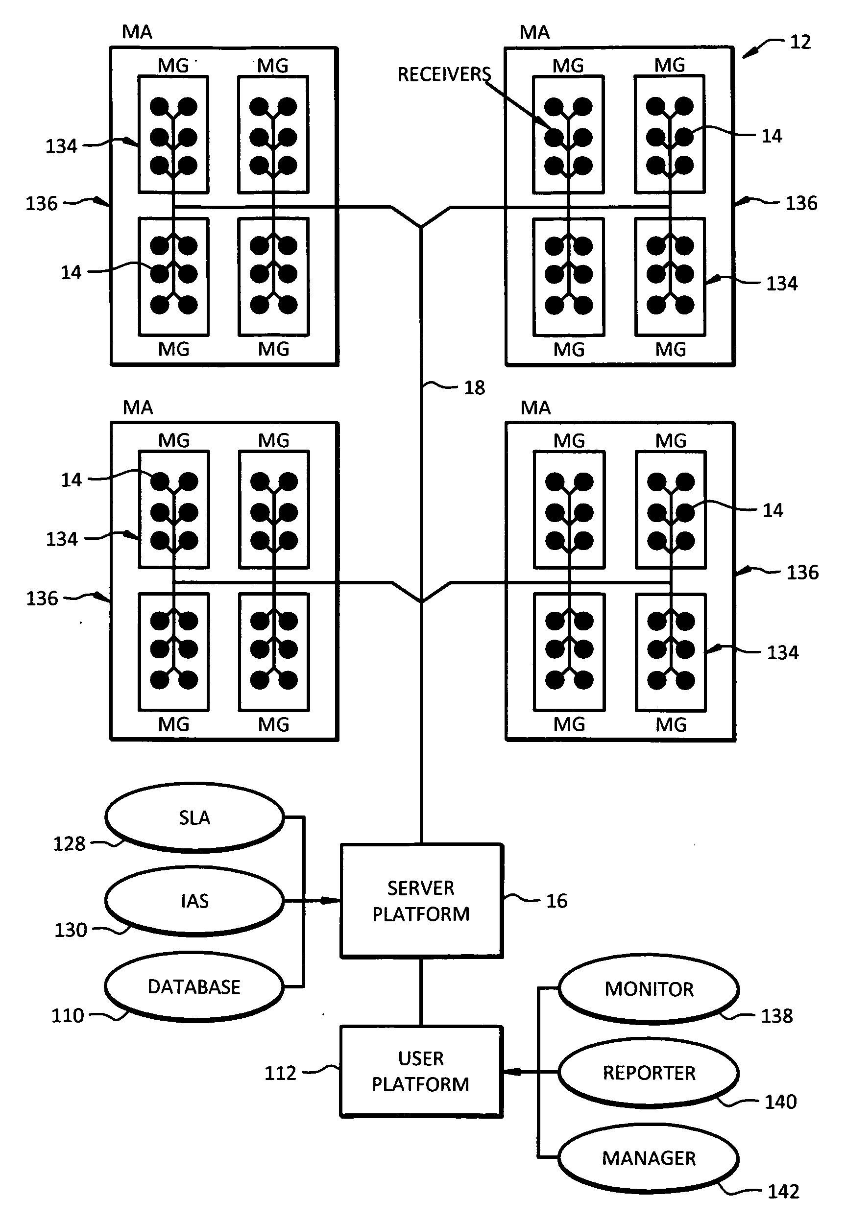
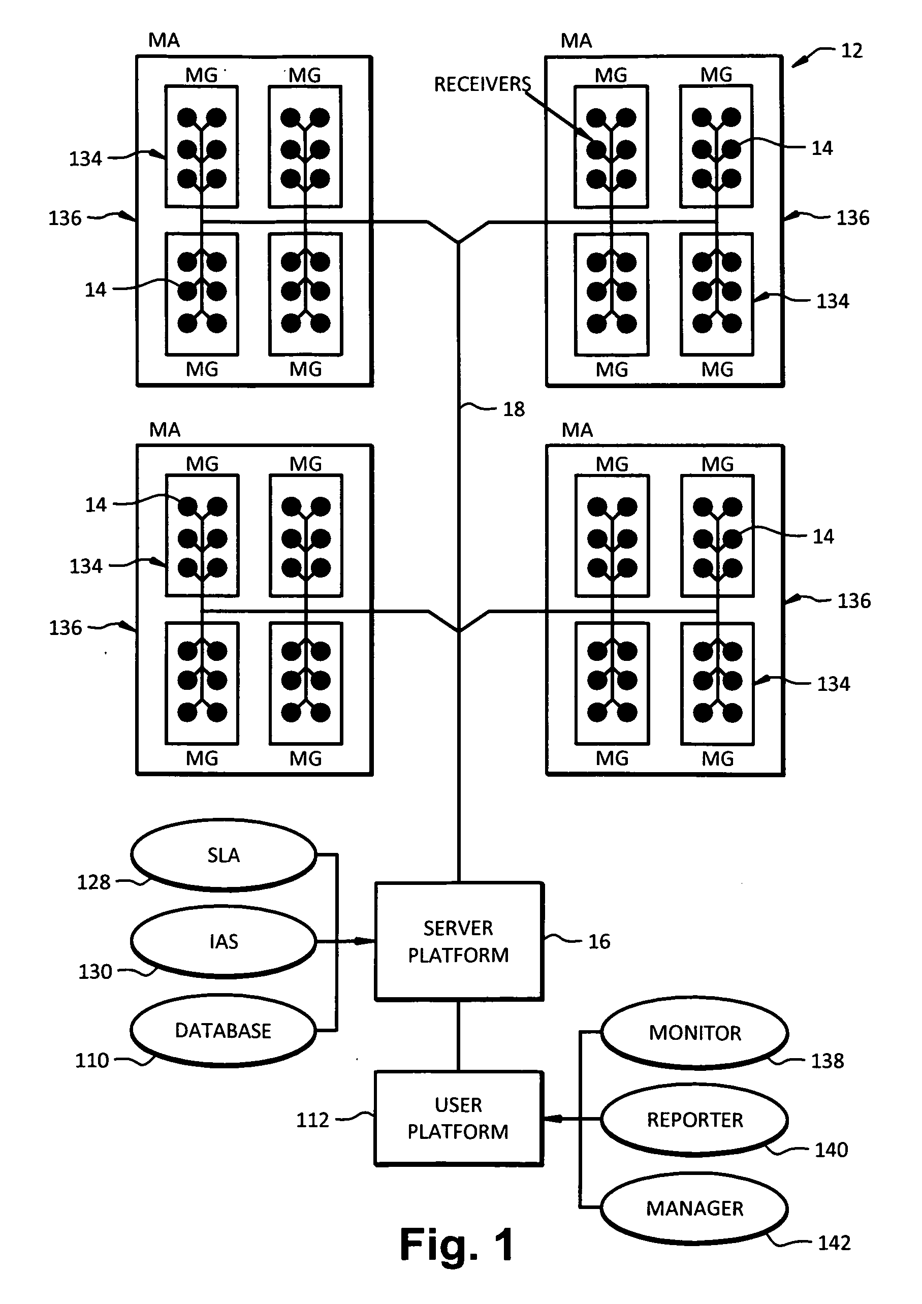
[0063]This embodiment of the present invention is a system 12 for the detection and location of illicit cell phone use, as illustrated in FIG. 1. The system 12 employs an array of radio frequency (RF) receivers 14 in known locations. These receivers 14 are connected to a central server 16 and communicate by using an Ethernet communication system 18. The server 16 runs software to control system operation and to determine the presence and location of any cell phones. A database 110 of relevant data and...


PUM


Abstract

A system for detecting and locating illicit cellular telephone use within a facility includes an array of radio frequency (RF) receivers, each receiver being placed in a predetermined location in the facility, and a central server, the receivers being in electrical communication with the central server. The server commands a group or groups of receivers to tune to a frequency of interest and to perform detailed sample rate measurements of the RF signal level received at the receivers. The array of receivers is organized into a plurality of measurement areas covering widely separated areas of the facility or different buildings of the facility, and the plurality of receivers of a measurement area is organized into a plurality of measurement groups covering areas of approximately uniform RF propagation conditions. Each receiver scans a frequency band of interest non-synchronously and independently of the other receivers in the array. Also, each receiver is preferably a direct-conversion receiver.

Description

CROSS REFERENCE TO RELATED APPLICATIONS[0001]This application is related to U.S. Provisional Application Ser. No. 60 / 852,385, which was filed on Oct. 17, 2006, and is entitled “Methodology and System to Prevent False Alarms from Nearby Areas Where Phone Use is Permitted”; U.S. Provisional Application Ser. No. 60 / 852,444, which was filed on Oct. 17, 2006, and is entitled “Methodology to Divide Facility Into Independent Regions for Accurate and Efficient Detection and Location of RF Sources”; U.S. Provisional Application Ser. No. 60 / 852,324, which was filed on Oct. 17, 2006, and is entitled “Use of an Integral Variable Attenuator to Identify Potential Harmonic Distortion Effects in a Direct-Conversion Receiver”; U.S. Provisional Application Ser. No. 60 / 852,440, which was filed on Oct. 17, 2006, and is entitled “Intermediate Frequency Response and Frequency Scanning Method to Minimize Measurement Interval with Direct-Conversion Frequency-Scanning Energy-Detection Receiver”; U.S. Provis...

Claims


Application Information

Patent Timeline
Patent Type & Authority Applications(United States)
IPC IPC(8): H04Q7/22H04W12/12H04W48/02H04W64/00H04W88/08
CPCH04W12/12H04W88/08H04W64/00H04W48/02H04W12/63
Inventor OLBERS, ROBERT L.LIU, YUAN-MINNESKY, MARK S.PLECAS, CRAIG A.REYES, JOSEPH L.KEIMIG, JOHNHORVATH, KENJI C.
Owner ITT MFG ENTERPRISES LLC
Why Eureka
Try Eureka