Rotary residual fuel slurrifier

Inactive Publication Date: 2008-07-24
FIREY JOSEPH CARL
View PDF5 Cites 10 Cited by
  • Summary
  • Abstract
  • Description
  • Claims
  • Application Information

AI Technical Summary

Problems solved by technology

Use of high viscosity, residual, petroleum fuels, in our surface transportation system, is currently limited to large bore, low speed, marine diesel engines.
Other surface transportation, such as railroads, tug and barge, trucks and buses, use small

Method used


Image

  • Rotary residual fuel slurrifier
  • Rotary residual fuel slurrifier
  • Rotary residual fuel slurrifier

Examples


Embodiment Construction

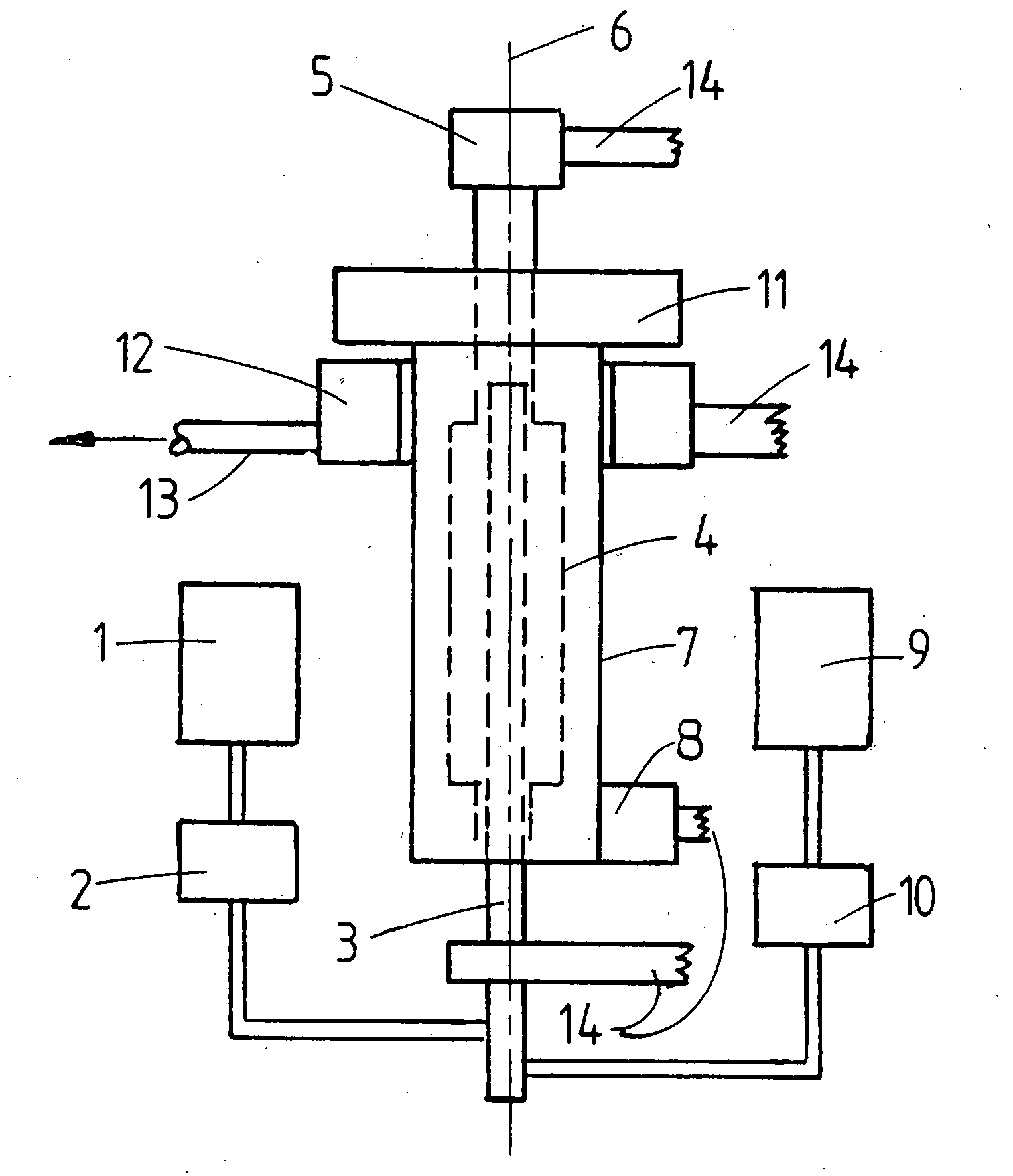
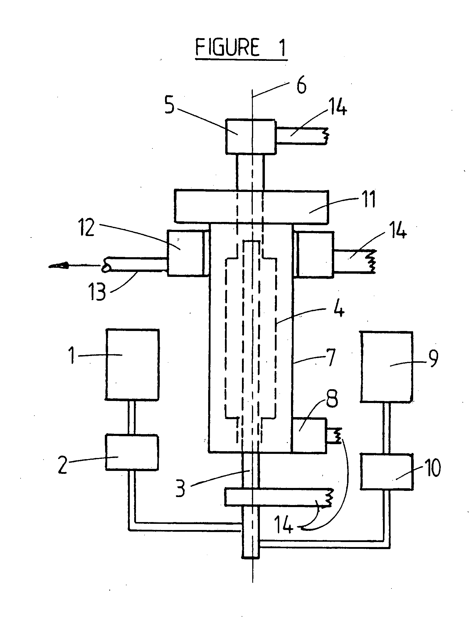
[0018]Rotary slurrifiers of this invention comprise at least one pair of discs, rotating at a high angular velocity as spinning discs, which apply centrifugal force to a first liquid, placed on the top surfaces of pairs of spinning discs, to accelerate the first liquid to a high velocity leaving the discs outer edge. This high velocity first liquid is thrown into counter-rotating, larger masses of second liquid within paired flow connected impact cavities, in a cavity shell counter-rotating at high angular velocity. The second liquid is essentially mutually insoluble in the first liquid. Each pair of spinning discs throws first liquid into a flow connected pair of rotating impact cavities containing the second liquid. In this way the impact forces in the paired cavities are counterbalanced.

[0019]The resulting high relative velocity between the first liquid entering into the larger mass of the second liquid in combination with the high density of a second liquid, creates strong atomi...


PUM

PropertyMeasurementUnit
Timeaaaaaaaaaa
Flow rateaaaaaaaaaa
Radiusaaaaaaaaaa

Abstract

A rotary slurrifier of this invention comprises a pair of spinning discs, which throw a first fluid into a larger mass of second fluid in paired and flow connected impact cavities, within a counter-rotating cavity shell. The first fluid is to be largely insoluble in the second fluid. Impact of the first fluid with the larger mass of second fluid, in the impact cavities, causes atomization of the first fluid into a slurry of many small first fluid particles suspended in a continuous phase of second fluid. The final slurry flows out of the rotating cavity shell via a slowdown reaction turbine.
High viscosity residual petroleum fuels and tars as first fluids can be thusly preatomized in a fuel in water slurry, and can then be cleanly and efficiently burned in small bore, high speed, diesel engines, which now require use of expensive low viscosity distillate fuels, which are in short supply.

Description

CROSS REFERENCES TO RELATED APPLICATIONS[0001]The invention described herein is directly related to my earlier filed U.S. Provisional Patent Application Ser. No. 60 / 881,860, filed 23 Jan. 2007, Joseph Carl Firey inventor, entitled, “Rotary Residual Fuel Slurrifier.” This material is incorporated herein by reference thereto.[0002]The invention described herein can be used beneficially in combination with the inventions described in my following related U.S. applications:[0003]A. “Supplementary Slurry Fuel Atomizer,” Provisional U.S. Patent Application Ser. No. 60 / 838,950, filed 21 Aug. 2006.[0004]B. “Common Rail Supplementary Atomizer for Piston Engines,” Provisional U.S. Patent Application Ser. No. 60 / 855,111, filed 30 Oct. 2006.[0005]C. “Supplementary Slurry Fuel Atomizer and Supply System,” U.S. patent application Ser. No. 11 / 633,107, filed 4 Dec. 2006.BACKGROUND OF THE INVENTION[0006]Use of high viscosity, residual, petroleum fuels, in our surface transportation system, is curren...

Claims


Application Information

Patent Timeline
IPC IPC(8): C10L3/00
CPCB01F3/0807B01F5/223C10L1/326C10L1/08C10L1/00B01F23/41B01F25/7411
Inventor FIREY, JOSEPH CARL
Owner FIREY JOSEPH CARL
Why Eureka
Try Eureka