Regenerative cryocooler, cylinder used for the regenerative cryocooler, cryopump, recondensing apparatus, superconducting magnet apparatus, and semiconductor detecting apparatus

a cryocooler and cylinder technology, applied in the field of regenerative cryocoolers and cylinders, can solve the problems of degrading cooling capacity, insufficient cooling capacity, and affecting the detection of semiconductors,

Inactive Publication Date: 2008-07-24
SUMITOMO HEAVY IND LTD
View PDF14 Cites 19 Cited by
  • Summary
  • Abstract
  • Description
  • Claims
  • Application Information

AI Technical Summary

Benefits of technology

[0017]Accordingly, embodiments of the present invention may provide a novel and useful regenerative cryocooler, cylinder used for the regenerative cryocooler, cryopump, recondensing apparatus, superconducting magnet apparatus, and semiconductor detecting apparatus, solving one or more of the problems discussed above.

Problems solved by technology

However, in the technique discussed in Japanese Laid-Open Patent Application Publication No. 2004-93062, although vibration is made in a direction where the vibration is reduced by the thick-wall parts 501a through 504a, this is not sufficient.
Furthermore, if a large number of the thick-wall parts 501a through 504a are provided in order to reduce the vibration, degradation of cooling capacity may be caused.
In addition, in the technique discussed in Japanese Laid-Open Patent Application Publication No. 2003-329324, while a vibration prevention effect may be expected, the cooling capability may be degraded.

Method used


Image

  • Regenerative cryocooler, cylinder used for the regenerative cryocooler, cryopump, recondensing apparatus, superconducting magnet apparatus, and semiconductor detecting apparatus
  • Regenerative cryocooler, cylinder used for the regenerative cryocooler, cryopump, recondensing apparatus, superconducting magnet apparatus, and semiconductor detecting apparatus
  • Regenerative cryocooler, cylinder used for the regenerative cryocooler, cryopump, recondensing apparatus, superconducting magnet apparatus, and semiconductor detecting apparatus

Examples


first embodiment

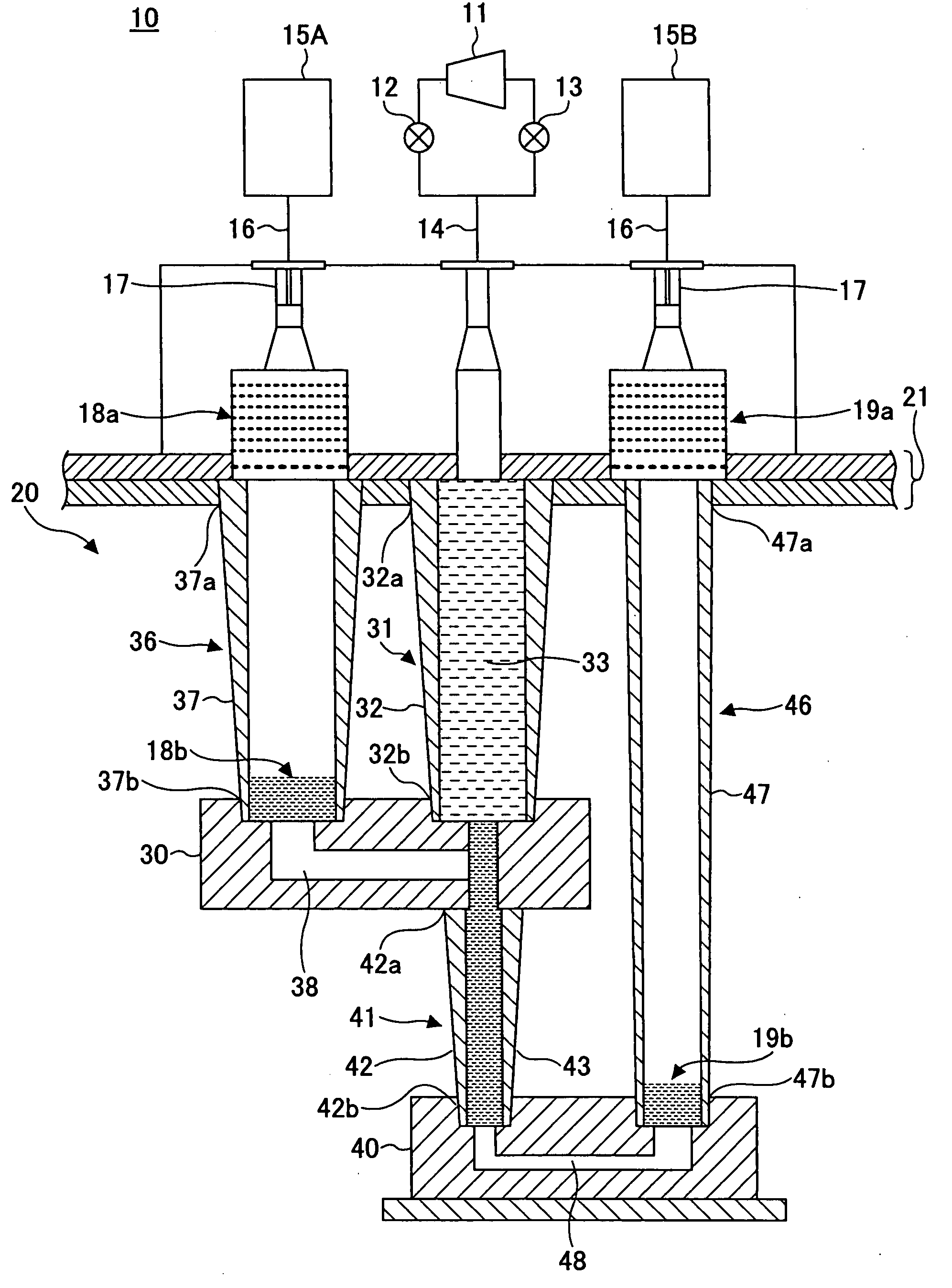
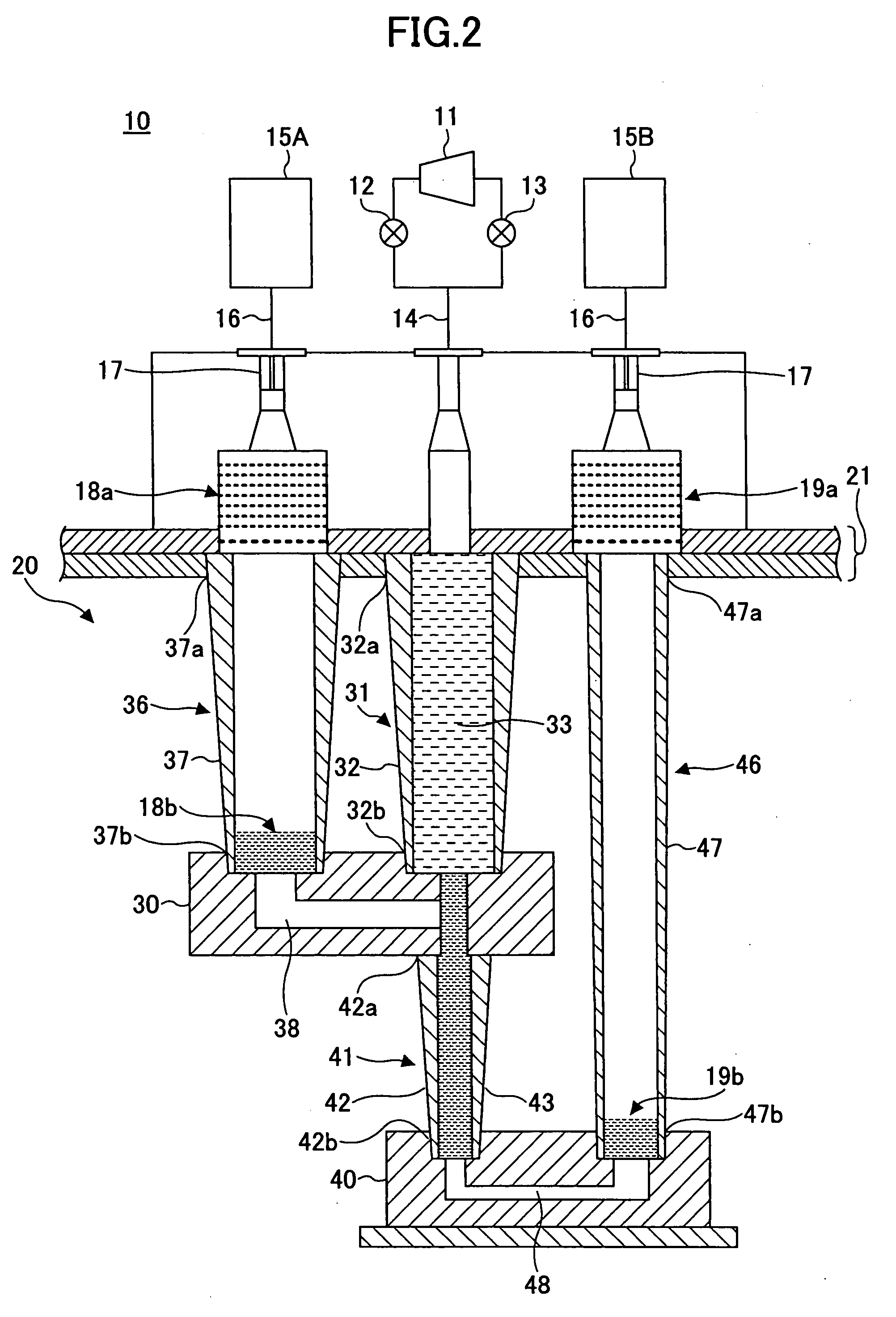
[0079]FIG. 2 is a schematic cross-sectional view of a pulse tube cryocooler of a first embodiment of the present invention.

[0080]Referring to FIG. 2, a pulse tube cryocooler 10 of a first embodiment of the present invention includes a gas compressor 11 and a two-stage type cold head 20. Helium gas is taken in and exhausted by the gas compressor 11 and a subject to be cooled (not shown in FIG. 20) can be cooled by the cold head 20. The cold head 20 includes a first stage regenerator tube 31, a first-stage pulse tube 36, a first stage cooling stage 30, a second stage regenerator tube 41, a second stage pulse tube 46, and a second stage cooling stage 40.

[0081]The first stage regenerator tube 31 includes a cylinder 32 made of, for example, stainless steel, and a regenerative material 33 formed by a metal mesh made of copper or stainless steel. The inside of the cylinder 32 is filled with the regenerative material 33. The first stage pulse tube 36 includes a hollow cylinder 37 made of, f...

second embodiment

[0143]FIG. 8 is a schematic cross-sectional view of a GM (Gifford-McMahon) cryocooler of a second embodiment of the present invention.

[0144]Referring to FIG. 8, a GM (Gifford-McMahon) cryocooler 60 of the second embodiment of the present invention includes a gas compressor 61 and a two-stage type cold head 66. Helium gas is taken in and exhausted from the gas compressor 61 so that the cold head 66 works as a cryocooler. The cold head 66 includes a first stage cooling part 70 and a second stage cooling part 80. The first stage cooling part 70 and the second stage cooling part 80 coaxially connect to a flange 68.

[0145]The first stage cooling part 70 includes a first stage cylinder 71, a first stage displacer 72, a first stage regenerator 78, a first stage expansion space 73, and a first stage cooling stage 75.

[0146]The first stage displacer 72 is provided so as to reciprocate in an axial direction in the first stage cylinder 71. The first stage regenerator 78 fills in the first stage ...

third embodiment

[0171]FIG. 9 is a schematic cross-sectional view of a Stirling cryocooler of a third embodiment of the present invention.

[0172]Referring to FIG. 9, the Stirling cryocooler of the third embodiment of the present invention includes a gas compressor 112 and a cold head 120. Working gas is taken in and exhausted from the gas compressor 110 via a capillary 101 so that the cold head 120 works as a cryocooler.

[0173]The gas compressor 110 includes a yoke 111, a dwelling vessel 112, and a compressing piston 113.

[0174]The yoke 11 includes a cylindrical-shaped groove forming part 118, a ring-shaped groove forming part 119, and a ring-shaped permanent magnet 116. The groove forming part 118 forms a cylinder of the compressing piston 113. A movable coil 115 fixed to the compressing piston 113 is inserted in the groove forming part 119. The permanent magnet 116 is embedded in an outside internal wall of the groove forming part 119. An outside electric power supply (not shown in FIG. 9) is connect...


PUM

PropertyMeasurementUnit
temperatureaaaaaaaaaa
cryogenic temperaturesaaaaaaaaaa

Abstract

A cylinder used for a cold head of a regenerative cryocooler, the cylinder includes an inside having a hollow-shaped configuration for a regenerative material, wherein the thickness of the cylinder at a high temperature end is greater than the thickness of the cylinder at a low temperature end.

Description

BACKGROUND OF THE INVENTION[0001]1. Field of the Invention[0002]The present invention generally relates to regenerative cryocoolers, cylinders used for the regenerative cryocoolers, cryopumps, recondensing apparatuses, superconducting magnet apparatuses, and semiconductor detecting apparatuses.[0003]More specifically, the present invention generally relates to a regenerative cryocooler, a cylinder, such as a regenerator tube or a pulse tube, used for the regenerative cryocooler, and, a cryopump, a recondensing apparatus, superconducting magnet apparatus, and a semiconductor detecting apparatus using the regenerative cryocooler.[0004]2. Description of the Related Art[0005]Regenerative cryocoolers form cryogenic temperatures of approximately 4 K through approximately 100 K and are used for cooling superconducting magnets or for cryopumps. The regenerative cryocooler includes a compressing part, an expanding part, and a heat exchanging part.[0006]The compressing part is configured to p...

Claims


Application Information

Patent Timeline
Patent Type & Authority Applications(United States)
IPC IPC(8): F25B9/00F25B19/00B01D8/00F17C5/02H01F1/00
CPCF17C2270/0527F25B9/10F25B9/145F25B2309/1408F25B2500/13F25B2309/1414F25B2309/1421F25B2309/1424F25B2309/1413
Inventor MITA, HISAEXU, MINGYAO
Owner SUMITOMO HEAVY IND LTD
Why Eureka
Try Eureka