Snowmobile with improved drive train

a drive train and snowmobile technology, applied in the field of snowmobiles, can solve the problems of increasing cumbersome connection of prior art pulleys to conventional jackshafts, and requiring numerous parts, so as to increase add weight and cost, and reduce the production cost of snowmobiles

Active Publication Date: 2008-07-24
BOMBARDIER RECREATIONAL PROD INC
View PDF12 Cites 22 Cited by
  • Summary
  • Abstract
  • Description
  • Claims
  • Application Information

AI Technical Summary

Problems solved by technology

The connection of the prior art pulley to a conventional jackshaft is therefore cumbersome and requires numerous parts, adding weight and cost to a snowmobile.
This increases the production cost of the snowmobile as well as increases the number of part to maintain in inventory.
Thus they remain heavy.

Method used


Image

  • Snowmobile with improved drive train
  • Snowmobile with improved drive train
  • Snowmobile with improved drive train

Examples


Embodiment Construction

)

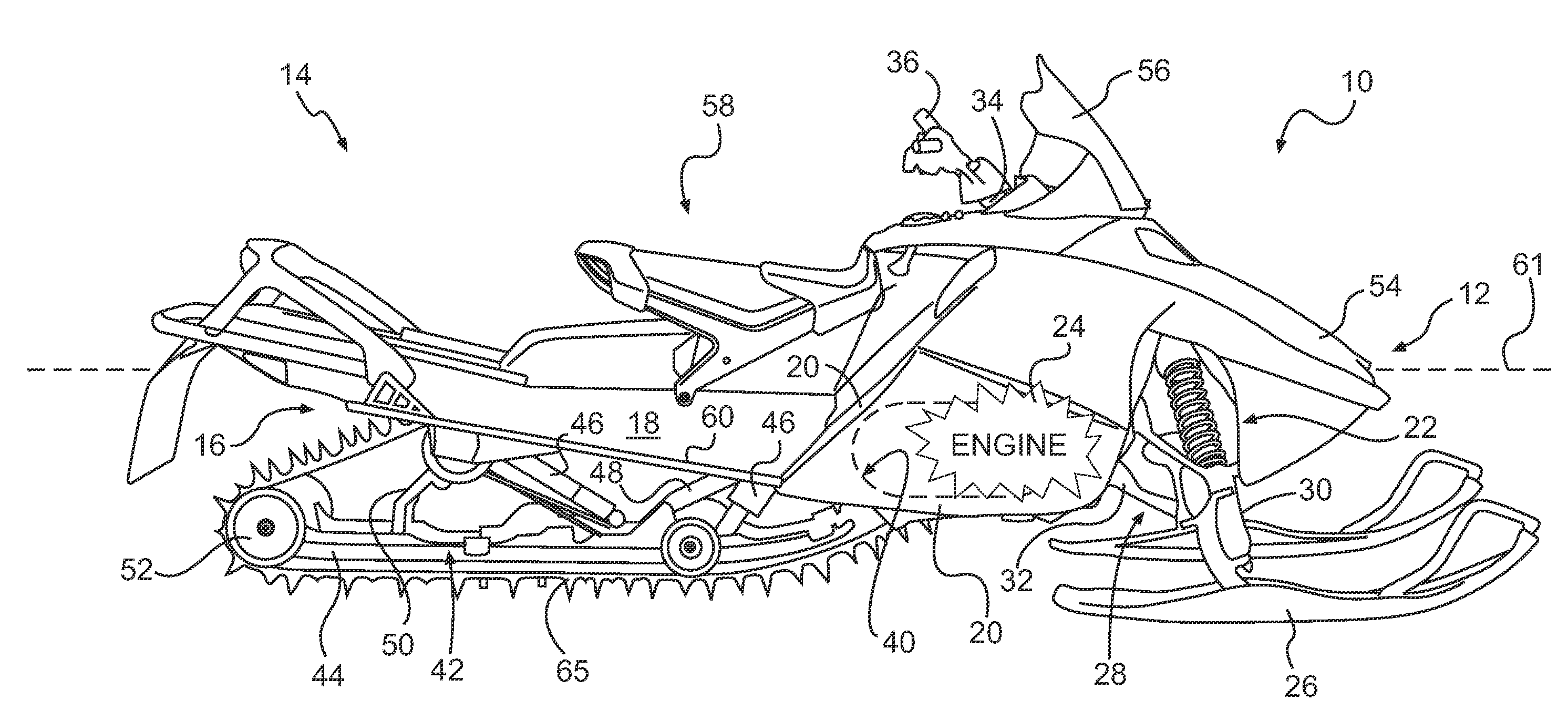
[0027]Referring now to FIG. 1, a snowmobile incorporating an embodiment of the present invention is designated generally by reference numeral 10. Although certain aspects of the present invention are applicable in other types of vehicles, the present invention has particular utility in connection with snowmobiles.

[0028]The snowmobile 10 includes a forward end 12 and a rearward end 14 which are defined consistently with a travel direction of the vehicle. The snowmobile 10 includes a frame 16 which normally includes a tunnel 18, an engine cradle portion 20 and a front suspension assembly portion 22. Tunnel 18 generally consists of an inverted U-shaped bent sheet metal which extends rearwardly along the longitudinal axis of the snowmobile 10 and is connected at the front to the engine cradle portion 20. An engine 24, which is schematically illustrated in FIG. 1, is carried by the engine cradle portion 20 of the frame 16. A steering assembly (not indicated) is provided, in which two sk...


PUM

PropertyMeasurementUnit
thicknessaaaaaaaaaa
thicknessaaaaaaaaaa
widthaaaaaaaaaa

Abstract

A snowmobile is disclosed having improved drive train including a continuously variable transmission (CVT) having a drive belt looped around a driving pulley and a driven pulley, and a transversely arranged jackshaft wherein the driven pulley is connected directly onto the outer surface of one end of the jackshaft. The transverse jackshaft is preferably made from a thin-walled hollow tube and the driven pulley is preferably press fitted thereon. A method of assembling a snowmobile drive train is also disclosed.

Description

FIELD OF THE INVENTION[0001]The present invention relates generally to a snowmobile and in particular to a snowmobile drive train.BACKGROUND OF THE INVENTION[0002]Conventional snowmobile drive trains incorporate a variable ratio belt drive system (commonly referred to as Continuously Variable Transmission or CVT) having a driving pulley that is directly coupled to the engine crankshaft and a driven pulley coupled to an output shaft. The driving pulley acts as a clutch and includes a centrifugally actuated adjusting mechanism through which the drive ratio of the belt drive is varied progressively as a function of the engine speed and the output torque of the driven pulley. Typically, the driven pulley is coupled to a transverse jackshaft which in turn drives the input member of a chain and sprocket reduction drive. The output of reduction drive is coupled to one end of the axle on which are located the drive track drive sprocket wheels. Conventional jackshafts are typically solid ste...

Claims


Application Information

Patent Timeline
Patent Type & Authority Applications(United States)
IPC IPC(8): B62M27/02F16H59/06B23P19/04
CPCB62M27/02Y10T29/53F16H9/18B62M2027/023B60K17/06B60K17/22B60Y2200/252
Inventor AITCIN, XAVIER-PIERREPITRE, JOELNOLET, YAN
Owner BOMBARDIER RECREATIONAL PROD INC
Why Eureka
Try Eureka