Motion-detecting module with a built-in light source

Inactive Publication Date: 2008-07-24
LITE ON SEMICON
View PDF1 Cites 22 Cited by
  • Summary
  • Abstract
  • Description
  • Claims
  • Application Information

AI Technical Summary

Benefits of technology

[0012]Hence, the light-emitting chip and the image-sensing chip are separately embedded in the same PCB and the present invention uses the reflection type light-guiding element or the total internal reflectio

Problems solved by technology

Hence, the prior art is complex in both manufacturing process and assembling process.
Besides, the illuminant-fixing mechanism

Method used


Image

  • Motion-detecting module with a built-in light source
  • Motion-detecting module with a built-in light source
  • Motion-detecting module with a built-in light source

Examples


Example

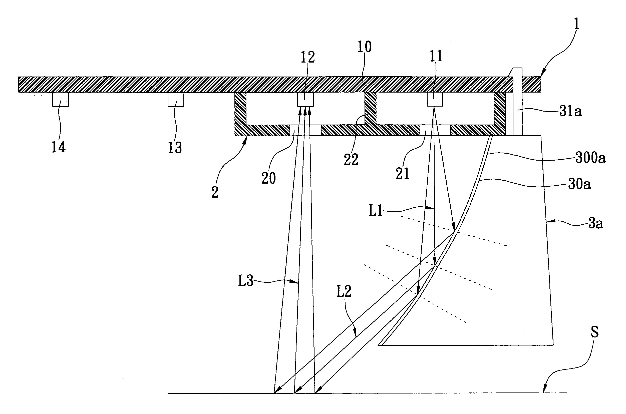
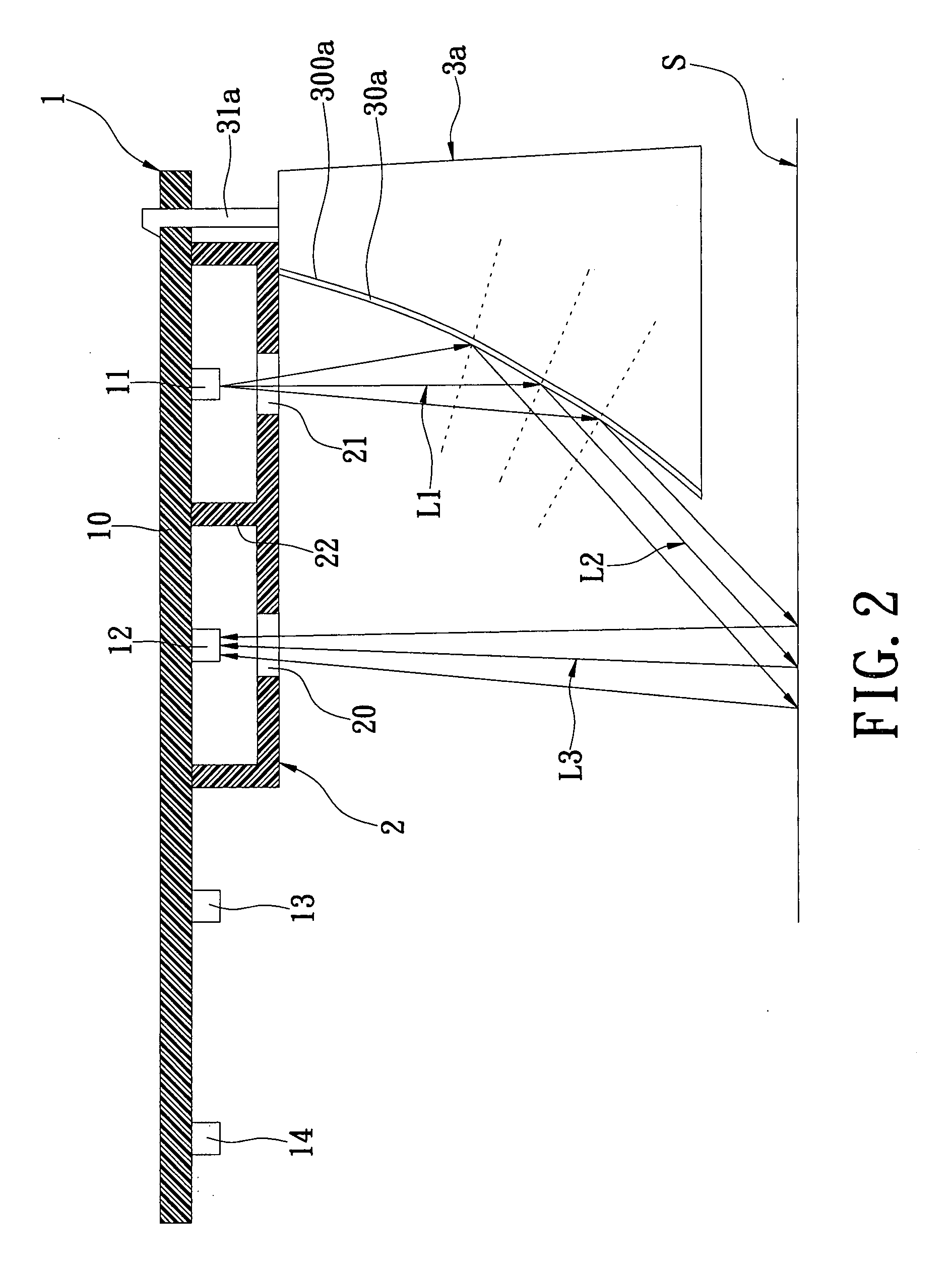
[0027]Referring to FIGS. 2 and 3, the first embodiment of the present invention provides a motion-detecting module with a built-in light source, comprising a chip unit 1, a cover unit 2, and a light-guiding unit 3a.

[0028]The chip unit 1 has a PCB (Printed Circuit Board) 10, a light-emitting chip 11, an image-sensing chip 12, a motion calculator ASIC (Application Specific Integrated Circuit) 13, and an interfacing MCU (Microprocessor Control Unit) 14 for communicating with external systems (not shown). The light-emitting chip 11, the image-sensing chip 12, the motion calculator ASIC 13, and an interfacing MCU 14 are electrically disposed on the PCB 10, respectively.

[0029]Moreover, the cover unit 2 is covered on the light-emitting chip 11 and the image-sensing chip 12. The cover unit 2 has a first opening 20 for exposing the image-sensing chip 12 and a second opening 21 for exposing the light-emitting chip 11.

[0030]Furthermore, the cover unit 2 has a partition 22 for dividing the lig...

Example

[0034]Referring to FIG. 4, the second embodiment of the present invention provides a motion-detecting module with a built-in light source. The difference between the second embodiment and the first embodiment is that the motion-detecting module has a light-guiding unit 3b. Moreover, the light-guiding unit 3b has a plurality of positioning elements 31b. Hence, the light-guiding unit 3b is positioned on the cover unit 2 via the positioning elements 31b.

Example

[0035]Referring to FIGS. 5 and 6, the third embodiment of the present invention provides a motion-detecting module with a built-in light source. The difference between the third embodiment and the first embodiment is that the motion-detecting module has a light-guiding unit 3c, which is a total internal reflection type light-guiding element. Moreover, the light-guiding unit 3c has a reflective surface 300c for reflecting and condensing beams L1′ that generate from the light-emitting chip 11. The total internal reflection type light-guiding element has a refractive index higher than that of air. The surface 300a is a concave structure. According to different requirements, the surface 300a can be a spherical surface, an aspherical surface, a paraboloid, a hyperboloid, or an ellipsoid. Furthermore, the light-guiding unit 3c has a plurality of positioning elements 31c. Hence, the light-guiding unit 3c is positioned on the PCB 10 of the chip unit 1 via the positioning elements 31c.

[0036...


PUM


Abstract

A motion-detecting module with a built-in light source includes a chip unit, a cover unit, and a light-guiding unit. The chip unit has a PCB, a light-emitting chip, and an image-sensing chip. The light-emitting chip and the image-sensing chip are electrically disposed on the PCB. The cover unit is covered on the image-sensing chip, and the cover unit has a first opening for exposing the image-sensing chip. The light-guiding unit is disposed on a bottom side of the cover unit, and the light-guiding unit has a surface having a reflective layer thereon with a concave structure. The surface and the reflective layer are formed a reflective surface for reflecting and condensing beams generated from the light-emitting chip. Therefore, the beams are reflected via the reflective surface to form first beams, and the first beams are reflected via the object surface to form second beams that project onto the image-sensing chip.

Description

BACKGROUND OF THE INVENTION[0001]1. Field of the Invention[0002]The present invention relates to a motion-detecting module, and particularly relates to a motion-detecting module with a built-in light source.[0003]2. Description of the Related Art[0004]FIG. 1 shows a cross-sectional, schematic view of an image-sensing device of the prior art. The image-sensing device of the prior art includes a main PCB (Printed Circuit Board) 1a, a light-emitting element 2a, an illuminant-fixing mechanism 3, an image-sensing element 4a, and a package casing 5a. [0005]The light-emitting element 2a is fixed on the illuminant-fixing mechanism 3 and is electrically connected with the main PCB 1a via a leading wire 20a. Moreover, the image-sensing element 4a is disposed on the main PCB 1a and is electrically connected with the main PCB 1a via a plurality of leading wire 40a. Furthermore, the package casing 5a covers on the image-sensing element 4a and has an opening hole 50a for exposing the image-sensin...

Claims


Application Information

Patent Timeline
IPC IPC(8): G01V8/14
CPCG01V8/14
Inventor CHENG, CHIA-CHUCHEN, JAU-YULIN, SHIH-HENG
Owner LITE ON SEMICON
Why Eureka
Try Eureka