
Easy-control valve

a valve and easy-to-control technology, applied in the direction of valve operating means/release devices, pressure relieving devices on sealing faces, transportation and packaging, etc., can solve the problems of long recovery delay, severe jeopardizing valve properties, etc., and achieves low cost, simple, robust

Inactive Publication Date: 2008-07-24
CHERN SHY SHIUN
View PDF6 Cites 15 Cited by
  • Summary
  • Abstract
  • Description
  • Claims
  • Application Information

AI Technical Summary

Benefits of technology

"The invention is a new valve design for low cost home gas safety systems. It is simple, robust, and easy to control. The valve uses a shortened switching length, a high pull force, and a circuit protection device. The invention also includes a hub with a detachable seal plate and a spring load to improve seal performance. Overall, the invention provides a better solution for gas safety than conventional valves."

Problems solved by technology

A conventional solenoid valve is doing so in a wrong way by reducing the plunger diameter of the valve to achieve a compromised control automation, which severely jeopardizes the properties of the valve.
It conditions a bimetallic switch to result in long recovery delay so that it prevents the solenoid from being stressed overtime.

Method used


Image

  • Easy-control valve
  • Easy-control valve
  • Easy-control valve

Examples


Embodiment Construction

[0033]It should be noted that like elements are denoted by the same reference numbers throughout the description. It should also be understood that the invention should not be limited to these embodiments. Although numerical values (such as mm, degrees, pounds, volts, amperes, ohms and turns) are used, they are used to illustrate the approximate values of preferred embodiments and not to limit the invention to the specific values. Illustration of design may be pushed to its extreme; however, principles presented remain valid in case of trade off adjustments for (tooling) cost minimization.

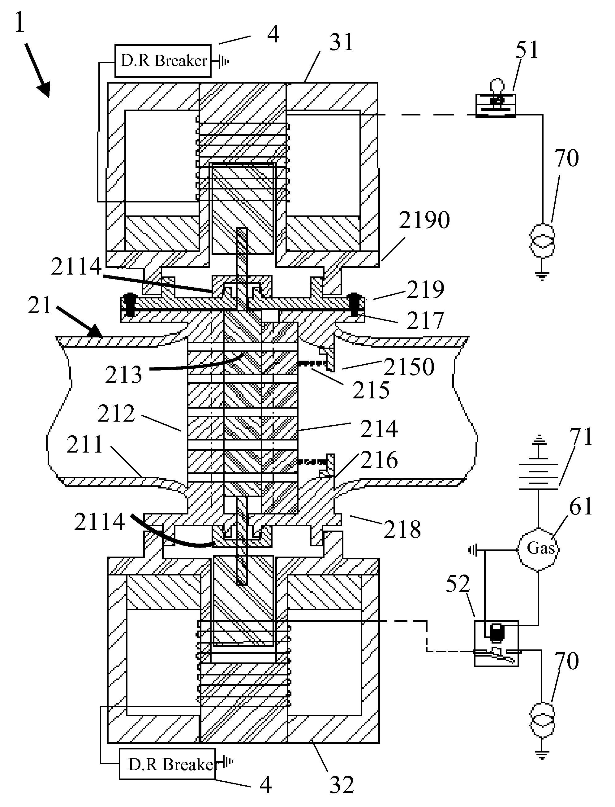
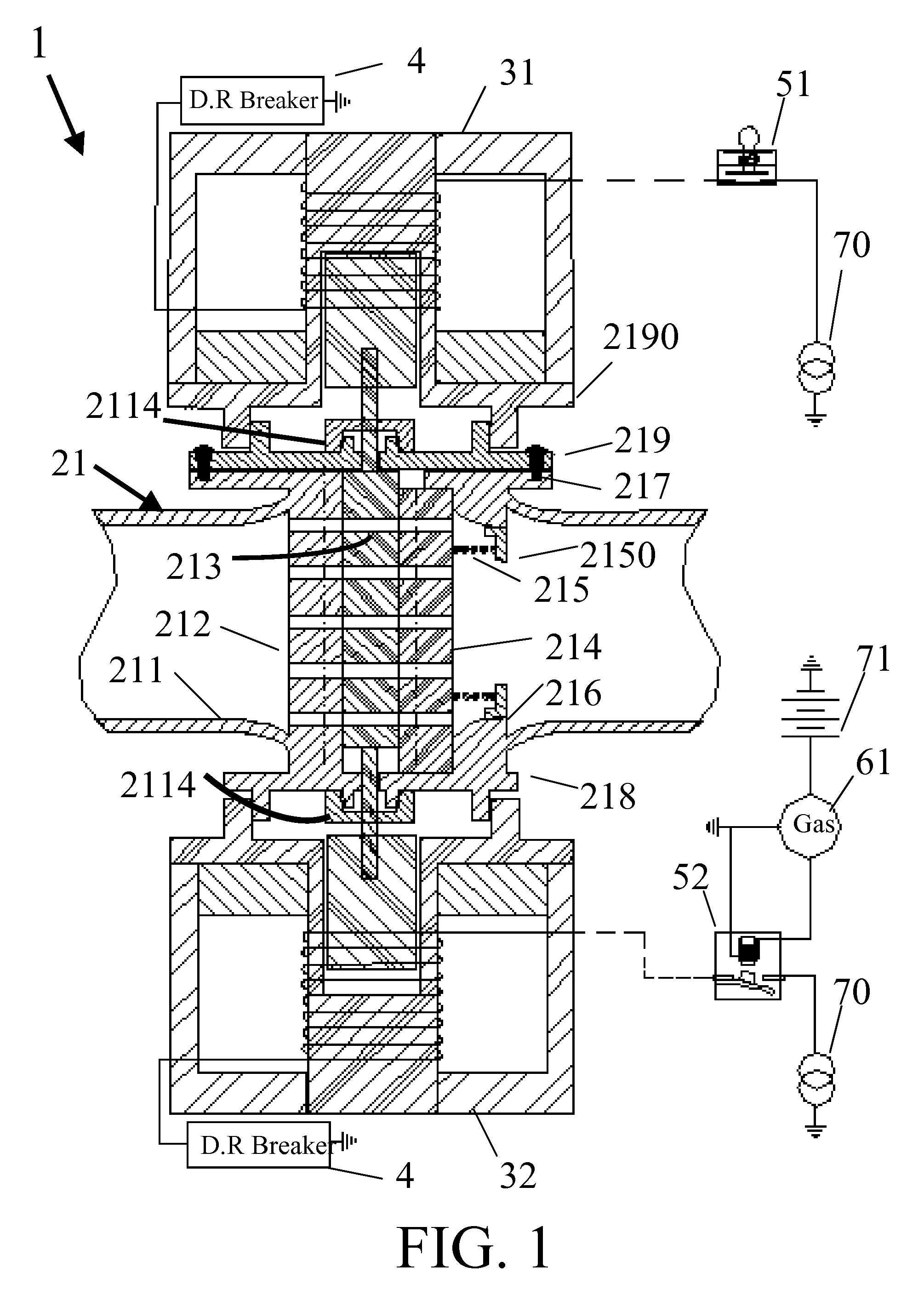
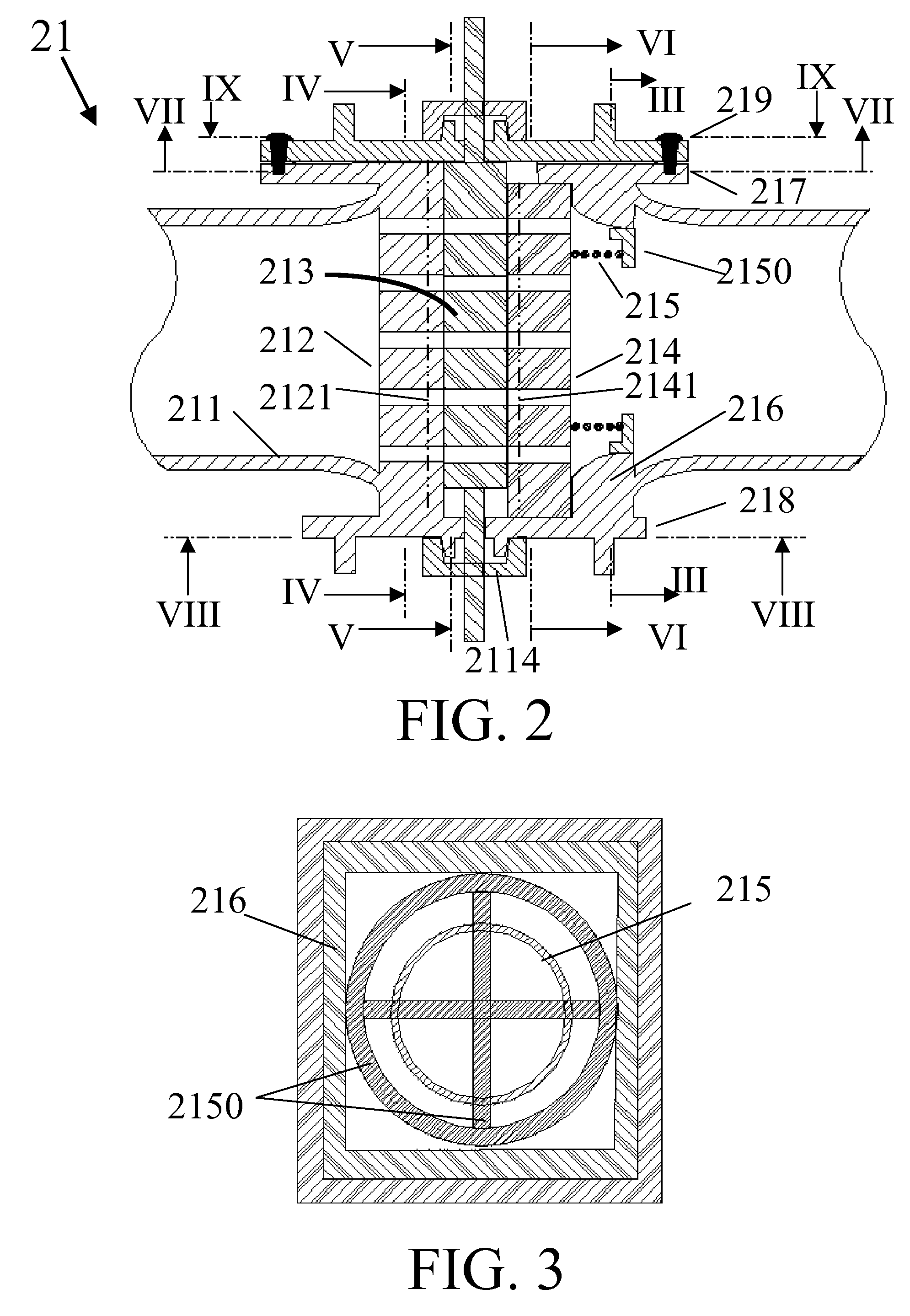
[0034]One embodiment of the invention is directed to a gate type EC valve that is shown as item 1 in FIG. 1. Item 1 comprises a SSL valve 21, and two solenoids 31 (to open) &32 (to Close) along with their protection circuits, delayed recovery automatic circuit breakers 4. The EC valve is to be inserted between the gas source pipe and a gas appliance, such as a stove. FIG. 1 illustrates a range safe...


PUM


Abstract

In a Valve, grid-patterned, fixed wall(s) and movable gate plate / plug are built in the hub to control the conduction area. Adjustable spring is applied to push the gate / plug firmly against the fixed wall(s). The structure alteration reduces the travel length required to switch the valve between open and closed states. Since the open / close state is self-sustaining at its last switched state due to friction, no holding energy is required in the actuator. Consequently, a small linear operation solenoid can be used in impulse mode to operate the valve. Due to its low cost, separate solenoids are used to respectively pull open and close the valve in lieu of applying an auto-direction-conversion mechanism. A bimetallic strip contact in series with a resister, packaged together in a thermal isolating tube, is used to prevent the low-duty solenoid from excessive stress-time.

Description

CROSS REFERENCE TO RELATED APPLICATION[0001]This application claims priority of U.S. Provisional Patent Application No. 60 / 881,661 filed on Jan. 22, 2007.BACKGROUND OF THE INVENTION[0002]1. Field of the Invention[0003]This invention relates to a gas safety valve, more specifically it relates to a valve, which helps the realization of low cost home gas safety systems so that home safety systems can be more affordable and widely utilized.[0004]2. Description of the Related Art[0005]Gas has become an item closely affecting our daily life. Due to its toxic and combustible nature, precaution is a necessity in all types of gas application.[0006]For self confined systems, such as a gas central air heater or a gas water heater, proper safety devices are incorporated in the appliances. The key safety component is a sophisticated gas valve, which is expensive, application specific, very fragile and requires physical protection if it is used as a standalone device.[0007]For non-self-confined s...

Claims


Application Information

Patent Timeline
Patent Type & Authority Applications(United States)
IPC IPC(8): F16K31/02
CPCF16K3/02F16K31/0668F16K3/34Y10T137/7761
Inventor CHERN, SHY-SHIUN
Owner CHERN SHY SHIUN
Learn More