
Temperature Detector And Recording Apparatus Including The Same

a technology of temperature detector and recording apparatus, which is applied in the direction of instruments, heat measurement, code conversion, etc., can solve the problems of reducing the responsiveness of the driver in temperature detection, the temperature of the driver ic further rising before one sweep is completed, and the driving efficiency of the driver is decreased, so as to reduce the responsiveness of temperature detection and the driving efficiency.

Active Publication Date: 2008-07-24
BROTHER KOGYO KK
View PDF6 Cites 13 Cited by
  • Summary
  • Abstract
  • Description
  • Claims
  • Application Information

AI Technical Summary

Benefits of technology

[0007]The above-described technique involves following two problems. First, since a sweep range is always a constant, wide temperature range, a sweep period is elongated which lowers responsiveness in temperature detection. That is, even though a temperature of the driver IC is detected, the detected temperature is outputted during a next sweep cycle. As a result, there is a possibility that the temperature of the driver IC further rises before one sweep is completed. Therefore, it is necessary to set a detection temperature to a lower value in anticipation of a sudden rise in temperature of the driver IC. In such a case, the driver IC is driven at a low temperature irrespective of a rate of temperature change. This decreases a driving efficiency.
[0008]Second, since a temperature of the driver IC is detected only when the driver IC reaches the detection temperature, it is necessary to set a detection temperature to a lower value in anticipation of a sudden rise in temperature of the driver IC. In such a case, the driver IC is driven at a low temperature. This decreases a driving efficiency. Here, adopting a D / A converter as a circuit for changing the reference voltage is known, which increases costs however. Thus, known is a technique of using a circuit which outputs a PWM signal, a circuit which smoothes the PWM signal and generate a reference voltage, and a circuit which modulates a pulse width of the PWM signal. This technique allows a reference voltage to be changed by a low-cost circuit configuration. However, in order to generate a stable reference voltage with few ripples, for improving temperature detection accuracy, the smoothing circuit needs to have a sufficiently large time constant. When a time constant of the smoothing circuit is made larger, a phase lag of the reference voltage becomes larger, which lowers responsiveness in temperature detection.
[0009]An object of the present invention is to provide a temperature detector and a recording apparatus which present high responsiveness in temperature detection.
[0010]Another object of the present invention is to provide a temperature detector and a recording apparatus which present high responsiveness in temperature detection while suppressing reduction in temperature detection accuracy.
[0012]In this aspect, values of the first signal level and the second signal level stored in the level memory are rewritten by the level rewriter in accordance with a temperature detected by the control circuit, so that a range of change in voltage of the reference signal is easily changed to an appropriate range corresponding to the level of the output signal of the temperature sensor. As a result, responsiveness in temperature detection can be improved.
[0014]In this aspect, the pulse signal generation circuit generates such a pulse signal that there are two or more kinds of patterns of periods during which the pulse signal is maintained at a high level in the predetermined cycle. Therefore, a plurality of spectra of the pulse signal is dispersed. At this time, by optimizing the smoothing circuit in accordance with a pulse cycle which corresponds to a spectrum dispersed in a higher frequency, a time constant of the smoothing circuit can be made smaller while suppressing occurrence of a ripple. Consequently, a phase lag of the reference signal can be suppressed. Therefore, responsiveness in temperature detection can be improved while suppressing deterioration in temperature detection accuracy.

Problems solved by technology

First, since a sweep range is always a constant, wide temperature range, a sweep period is elongated which lowers responsiveness in temperature detection.
As a result, there is a possibility that the temperature of the driver IC further rises before one sweep is completed.
This decreases a driving efficiency.
Here, adopting a D / A converter as a circuit for changing the reference voltage is known, which increases costs however.
When a time constant of the smoothing circuit is made larger, a phase lag of the reference voltage becomes larger, which lowers responsiveness in temperature detection.

Method used


Image

  • Temperature Detector And Recording Apparatus Including The Same
  • Temperature Detector And Recording Apparatus Including The Same
  • Temperature Detector And Recording Apparatus Including The Same

Examples


first embodiment

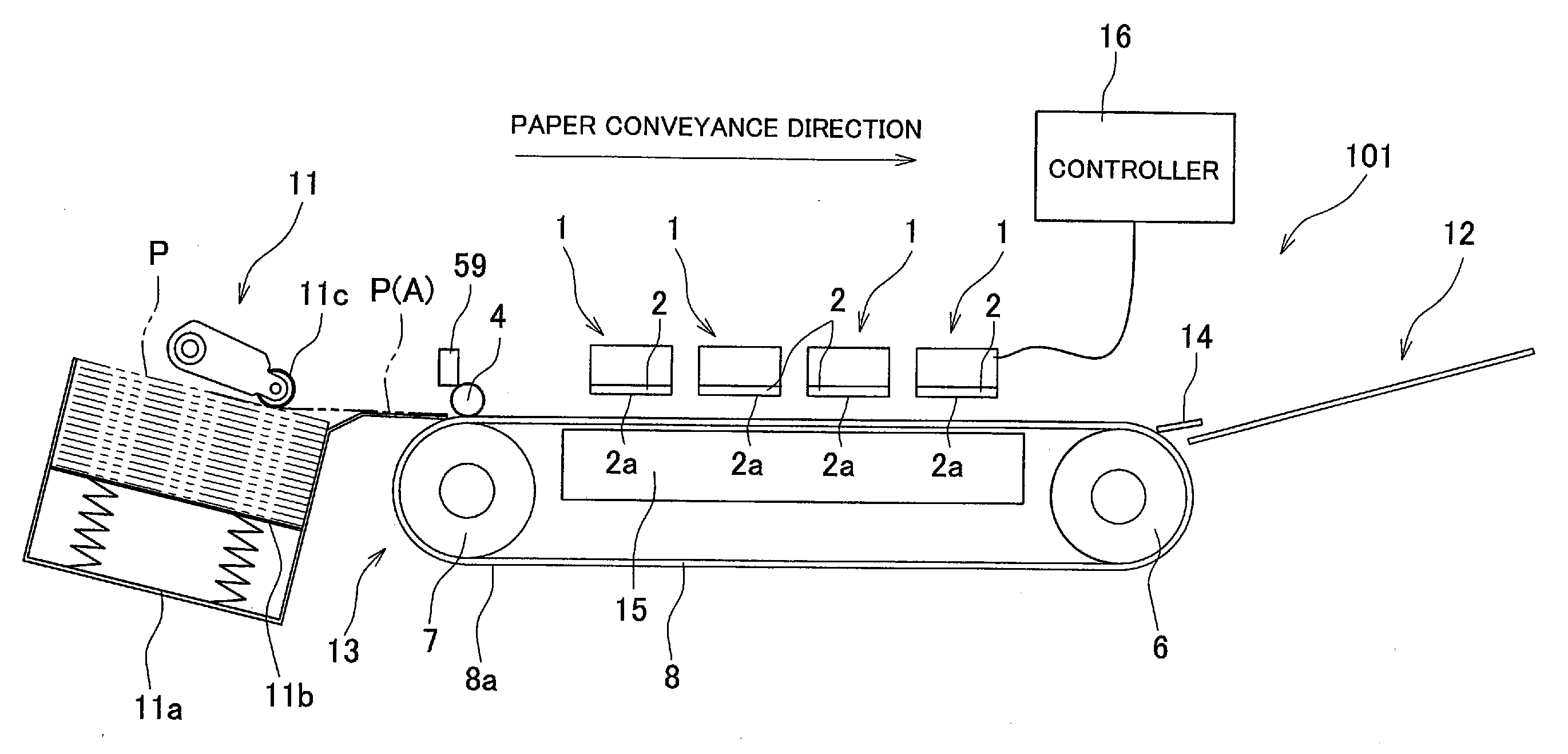
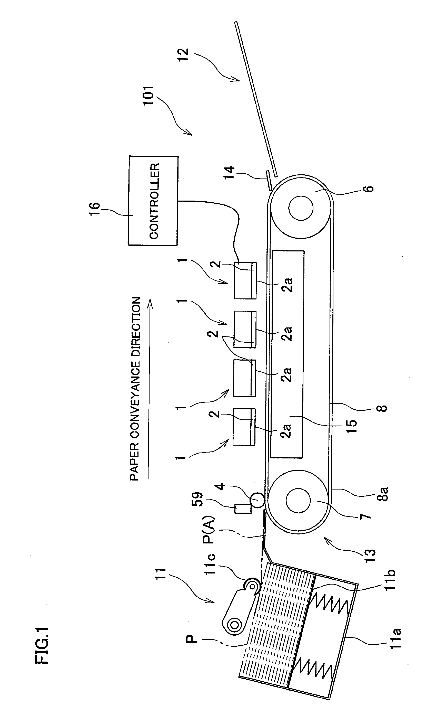
[0032]FIG. 1 is a side view of an ink-jet printer which is a recording apparatus including a temperature detector according to a first embodiment of the present invention. As shown in FIG. 1, an ink-jet printer 101 which is a recording apparatus is a color ink-jet printer including four ink-jet heads 1 which mean recording heads. The ink-jet printer 101 has a controller 16 which controls an operation of a whole of the ink-jet printer 101. The ink-jet printer 101 includes a paper feed unit 11 and a paper discharge tray 12, which are shown in left and right parts of FIG. 1, respectively.

[0033]Formed within the ink-jet printer 101 is a paper conveyance path through which a paper P which is a recording medium is conveyed from the paper feed unit 11 toward the paper discharge tray 12. The paper feed unit 11 has a paper stocker 11a and a pick-up roller 11c. The paper stocker 11a, which accommodates a plurality of papers P therein, is disposed in such a manner that its opening which opens ...

second embodiment

[0099]Next, a second embodiment of the present invention will be described with reference to FIG. 12. FIG. 12 is a block diagram of a PWM signal generation circuit 41 and a PWM controller 142. The second embodiment differs from the first embodiment only in a repeat counter 184 of the PWM controller 142. In the following, therefore, a description will be given mainly to the repeat counter 184, and the other parts of the ink-jet printer and the temperature detector will be denoted by the same reference numerals as in the first embodiment, without specific descriptions thereof.

[0100]The repeat counter 184 outputs an increment signal to a sweep counter 83 so as to change a reference voltage step by step from a minimum reference voltage to a maximum reference voltage by the number of repeat times which is indicated by a repeat-time signal Repeat inputted. The increment signal is outputted in every sampling period which is based on the number of PWM pulses.

[0101]More specifically, the rep...

third embodiment

[0110]Next, a third embodiment of the present invention will be described with reference to FIGS. 13 to 15. FIG. 13 is a view showing this embodiment and corresponding to FIG. 6 for the first embodiment. FIG. 14 is a block diagram of a PWM signal generation circuit 441 and a PWM controller 42 which form a temperature detector of this embodiment. FIG. 15 is a view for explaining a PWM signal which is generated by the PWM signal generation circuit 441. This embodiment differs from the first embodiment only in the PWM signal generation circuit 441. In the following, therefore, a description will be given mainly to the PWM signal generation circuit 441, and the other parts of the ink-jet printer and the temperature detector will be denoted by the same reference numerals as in the first embodiment, without specific descriptions thereof.

[0111]In this embodiment, the PWM signal generation circuit 441 generates a Pulse Width Modulation (PWM) having only a single pulse within a predetermined...


PUM


Abstract

A temperature detector of the present invention includes a temperature sensor, a reference signal generation circuit, a level memory which rewritably stores therein a first signal level and a second signal level, a control circuit which controls the reference signal generation circuit so as to make a level of the reference signal change from the first signal level to the second signal level, a comparator circuit which compares the level of the reference signal and a level of the output signal, and a level rewriter which rewrites at least either one of the first signal level and the second signal level. When the level of the reference signal reaches the level of the output signal, the control circuit generates a detected temperature signal, and controls the level rewriter so as to change a range where a level of the reference signal changes.

Description

CROSS REFERENCE TO RELATED APPLICATION[0001]The present application claims priority from Japanese Patent Applications No. 2006-336094 and No. 2006-336095, which were both filed on Dec. 13, 2006, the disclosures of which are herein incorporated by reference in their entirety.BACKGROUND OF THE INVENTION[0002]1. Field of the Invention[0003]The present invention relates to a temperature detector which detects a temperature of a detection object, and also to a recording apparatus including the temperature detector.[0004]2. Description of Related Art[0005]There is an ink-jet printer which prints an image on a recording paper by ejecting ink droplets on the recording paper as a recording medium. As such an ink-jet printer, one including a recording head and a driver IC is known. The recording head has a passage unit in which nozzle for ejecting ink droplets and pressure chambers communicating with the nozzles are formed, and an actuator unit which applies ejection energy to ink contained i...

Claims


Application Information

Patent Timeline
Patent Type & Authority Applications(United States)
IPC IPC(8): B41J29/393
CPCB41J2/04563B41J2/04581G01K3/005H03M1/822G01K2219/00H03M1/504G01K13/00
Inventor SUZUKI, KATSUAKI
Owner BROTHER KOGYO KK
Learn More