
Electrostatic chuck with heater and manufacturing method thereof

Active Publication Date: 2008-07-24
NGK INSULATORS LTD
View PDF6 Cites 62 Cited by
  • Summary
  • Abstract
  • Description
  • Claims
  • Application Information

AI Technical Summary

Benefits of technology

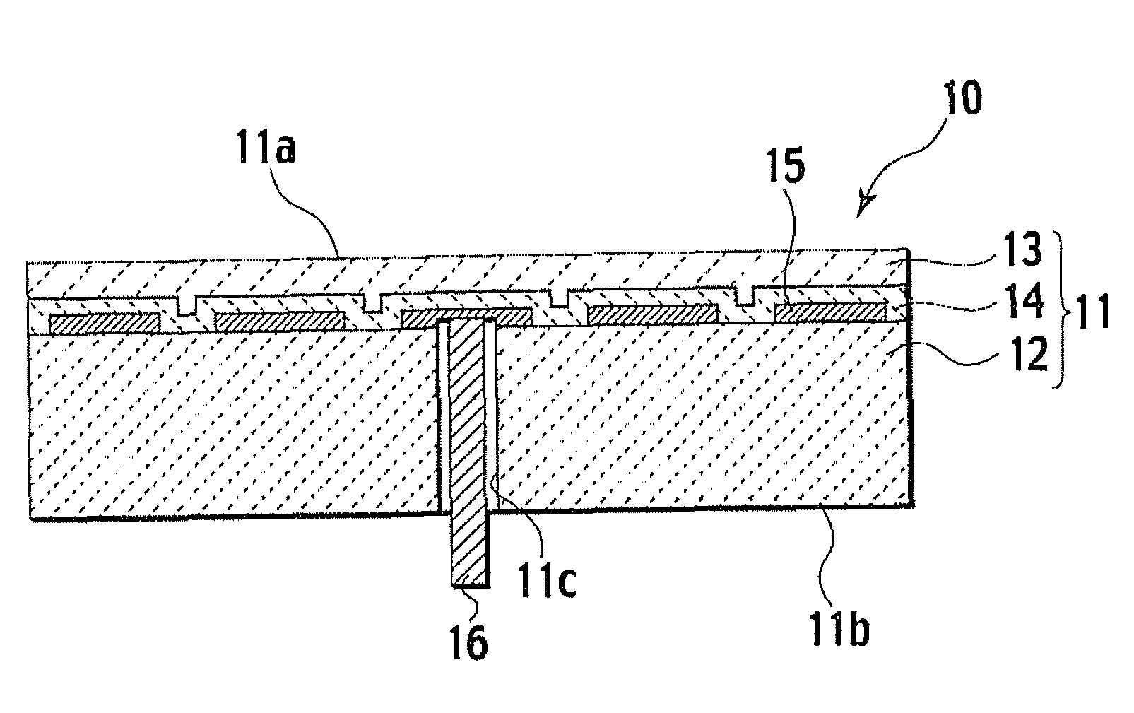
[0013]In the electrostatic chuck according to the present invention, the carbon content in alumina ceramics in contact with the dielectric electrode is 0.05 wt % or less, thus making it possible to effectively suppress the leak current from the dielectric electrode. Moreover, the bonding strength of alumina ceramics to yttria ceramics is enhanced, whereby excellent suction force is exerted, and the ESC characteristics are less likely to be deteriorated even after a long-time use of the electrostatic chuck. Moreover, yttria ceramics having high corrosion resistance is formed on the surface of the base, and accordingly, the electrostatic chuck according to the present invention has excellent corrosion resistance even under the severe corrosive environment.

Problems solved by technology

However, since carbon has conductivity, when the ceramic member is applied to the electrostatic chuck, there has been a case where the volume resistivity of alumina is decreased by a high temperature in an environment where the electrostatic chuck is used.
There has been an apprehension that the increase of the leak current may cause a malfunction particularly in the case of an electrostatic chuck in which the dielectric electrode is disposed in a bonded portion between the alumina sintered body and the yttria sintered body.
Accordingly, in the electrostatic chuck in which the above-described yttria sintered body is formed only on the upper surface of the base, corrosion resistance of a side surface portion thereof is not always sufficient depending on etching conditions, and there has been a case where the insufficient corrosion resistance causes contaminations and particles.

Method used


Image

  • Electrostatic chuck with heater and manufacturing method thereof
  • Electrostatic chuck with heater and manufacturing method thereof
  • Electrostatic chuck with heater and manufacturing method thereof

Examples


example 1

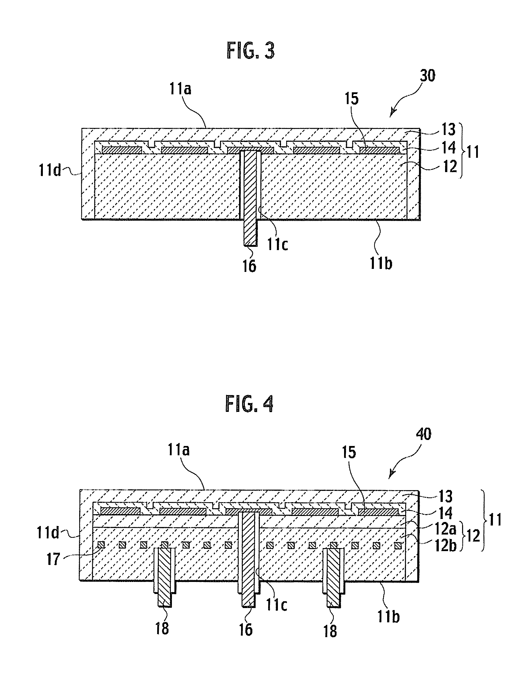
[0114]Example 1 is an example of manufacturing the electrostatic chuck shown in FIG. 3 in accordance with the steps shown in FIG. 5A to FIG. 5F.

[0115]As the raw material powder of the alumina sintered body, alumina powder with a purity of 99.9 wt % and an average particle diameter of 0.5 μm was prepared. To the alumina powder, there were added water, a dispersant, and polyvinyl alcohol (PVA) as a binder. Then, a resultant was mixed by a trommel for 16 hours, and raw material slurry was prepared. The obtained raw material slurry was shifted through a sieve with an aperture of 20 μm, and impurities were removed therefrom. Then, the slurry was sprayed and dried by using the spray dryer, and granules of alumina with an average particle diameter of approximately 80 μm were prepared. The granules thus obtained were calcined at 500° C. in an atmospheric pressure oxidation furnace.

[0116]Next, the granules of alumina were filled into the metal mold, and were pressed with 50 kgf / cm2 by a unia...

example 2

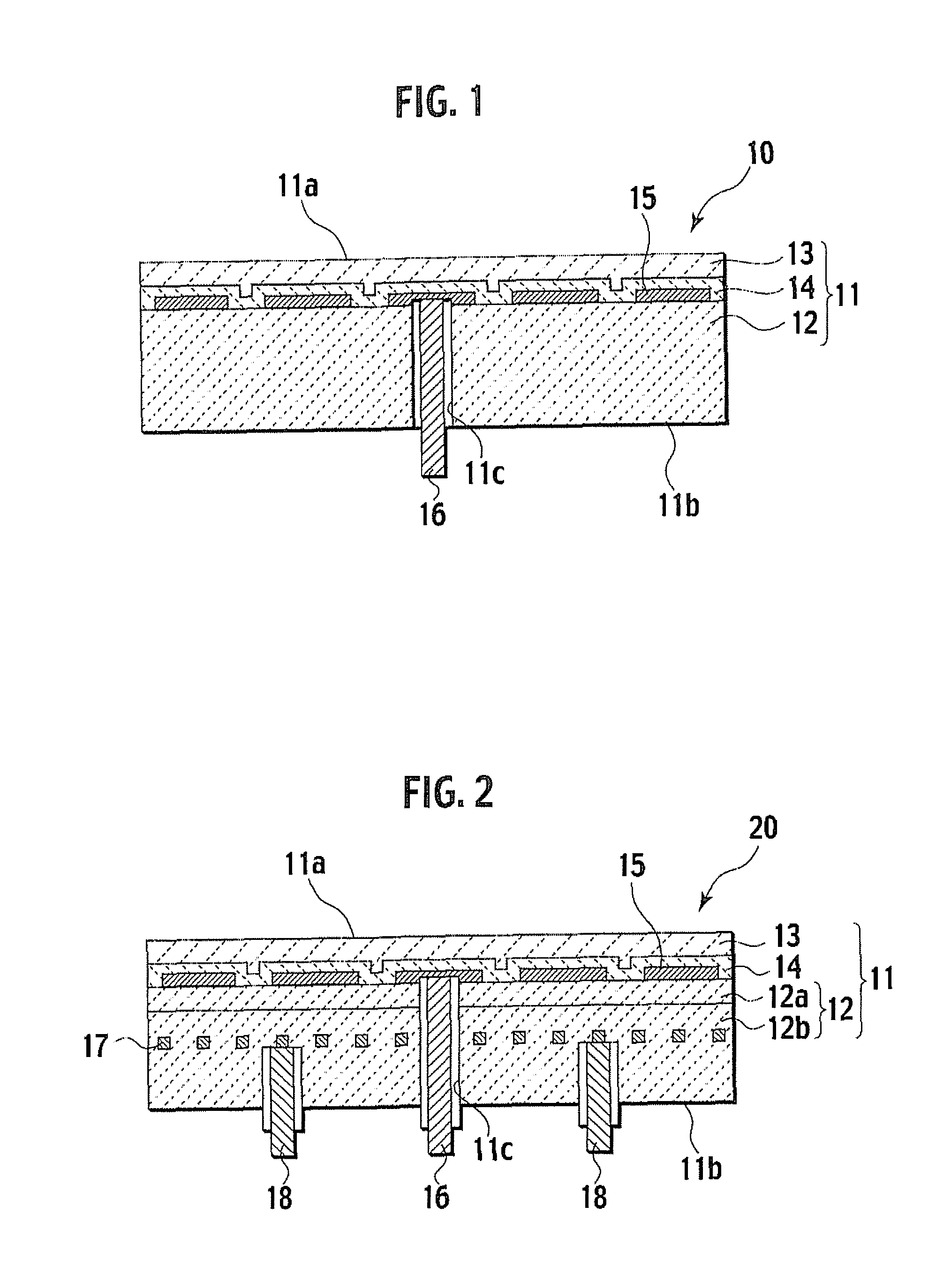
[0123]Example 2 is an example of manufacturing the electrostatic chuck with a heater in accordance with the steps shown in FIG. 6A to FIG. 5F.

[0124]As the raw material powder of the alumina sintered body, alumina powder with a purity of 99.9 wt % and an average particle diameter of 0.5 μm was prepared. To the alumina powder, there were added water, a dispersant, and polyvinyl alcohol (PVA) as a binder. Then, a resultant was mixed by the trommel for 16 hours, and raw material slurry was prepared. The obtained raw material slurry was shifted through the sieve with an aperture of 20 μm, and impurities were removed. Then, the slurry was sprayed and dried by using the spray dryer, and granules of alumina with an average particle diameter of approximately 80 μm were prepared. The granules thus obtained were calcined at 500° C. in the atmospheric pressure oxidation furnace.

[0125]Next, the granules of alumina were filled into the metal mold, and were pressed with 50 kgf / cm2 by the uniaxial ...

example 3

[0142]Example 3 is an example of manufacturing the electrostatic chuck with a heater, which is shown in FIG. 4.

[0143]As the raw material powder of the alumina sintered body, alumina powder with a purity of 99.9 wt % and an average particle diameter of 0.5 μm was prepared. To the alumina powder, there were added water, a dispersant, and polyvinyl alcohol (PVA) as a binder. Then, a resultant was mixed by the trommel for 16 hours, and raw material slurry was prepared. The obtained raw material slurry was shifted through the sieve with an aperture of 20 μm, and impurities were removed. Then, the slurry was sprayed and dried by using the spray dryer, and granules of alumina with an average granule diameter of approximately 80 μm were prepared. A carbon amount of the obtained granules was 1.2 wt % to 1.8 wt %.

[0144]Next, a part of the obtained granules was separated by a predetermined amount, and the predetermined amount of the granules was calcined at 500° C. in the atmospheric pressure ...


PUM

PropertyMeasurementUnit
Temperatureaaaaaaaaaa
Lengthaaaaaaaaaa
Lengthaaaaaaaaaa

Abstract

An electrostatic chuck includes a base. The base has a support portion made of alumina ceramics, and a surface portion made of yttria ceramics. The surface portion forms at least a substrate mounting surface and side surface of the base on a surface of the support portion. Carbon contents in alumina ceramics of the support portion and yttria ceramics of the surface portion are 0.05 wt % or less.

Description

CROSS-REFERENCE TO RELATED APPLICATION[0001]This application is based upon and claims the benefit of priority from Patent Application No. 2006-247685 filed on Sep. 13, 2006, in the Japanese Patent Office, of which contents are incorporated herein by reference.BACKGROUND OF THE INVENTION[0002]1. Field of the Invention[0003]The present invention relates to an electrostatic chuck and a manufacturing method thereof.[0004]2. Description of the Related Art[0005]Heretofore, in a manufacturing apparatus of a semiconductor device and a manufacturing apparatus of a liquid crystal device, an electrostatic chuck has been used in order to hold a substrate during a manufacturing process, for example, a deposition process and an etching process, and in order to convey the substrate. In general, the electrostatic chuck has a structure in which a dielectric electrode for generating electrostatic force is embedded in a base made of ceramics. Moreover, there is also an electrostatic chuck in which a r...

Claims


Application Information

Patent Timeline
IPC IPC(8): H01L21/683C04B35/10C04B35/505B29C67/04
CPCB29C43/006H01L21/6831C04B35/111C04B35/505C04B35/5626C04B35/62695C04B35/645C04B37/001C04B2235/3217C04B2235/6562C04B2235/6584C04B2235/721C04B2235/77C04B2235/96C04B2235/9607C04B2237/34C04B2237/343B29C67/04B32B18/00H01L21/67H01L21/68
Inventor HATTORI, AKIYOSHINOBORI, KAZUHIRO
Owner NGK INSULATORS LTD
Learn More