Multilayer capacitor and electronic device
- Summary
- Abstract
- Description
- Claims
- Application Information
AI Technical Summary
Benefits of technology
Problems solved by technology
Method used
Image

Examples
first embodiment
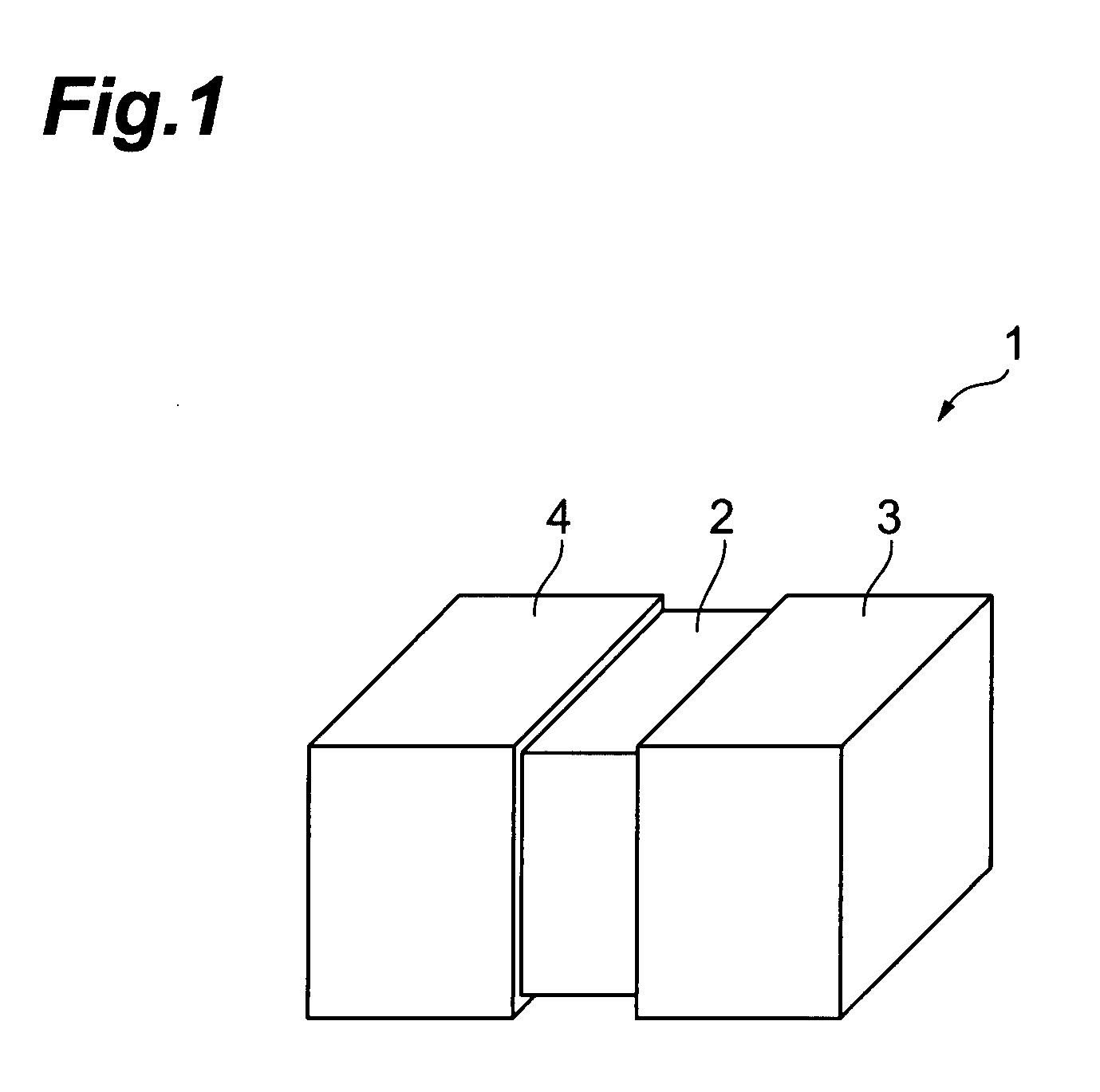
[0032]FIG. 1 is a perspective view showing the multilayer capacitor according to the In the same drawing, the multilayer capacitor 1 of the present embodiment has a laminate body 2 of a rectangular parallelepiped shape (which encompasses a nearly rectangular parallelepiped shape as well as a perfect rectangular parallelepiped shape), a terminal electrode 3 disposed on one longitudinal end side of this laminate body 2, and a terminal electrode 4 disposed on the other longitudinal end side of the laminate body 2.
[0033]The terminal electrode 3 is provided so as to cover one end face of the laminate body 2 and one-end-face-side portions in the four side faces of the laminate body 2, and the terminal electrode 4 is provided so as to cover the other end face of the laminate body 2 and other-end-face-side portions in the four side faces of the laminate body 2. The terminal electrodes 3, 4 are made, for example, by forming a Ni-plated layer and a Sn-plated layer in order on a baked electro...
third embodiment
[0068]Namely, the multilayer capacitor has the four resonance frequencies fr1-fr4, as in the third embodiment, and thus can achieve the low impedance across a sufficiently wide frequency band.
[0069]The above-described embodiment used the four types of internal electrodes connected to the terminal electrode 4, but the types of internal electrodes connected to the terminal electrode 4 may be three types, or five or more types, of course.
[0070]FIG. 10 is a sectional view showing the internal electrode layers in the multilayer capacitor according to the fifth embodiment. In the drawing, identical or equivalent elements to those in the first embodiment will be denoted by the same reference symbols, without redundant description.
[0071]In the same drawing, the laminate body 2 of the multilayer capacitor of the present embodiment has a structure in which internal electrode layers 51-53 are alternately laminated from the bottom in each of plural groups with a dielectric layer 9 in between.
[0...
fourth embodiment
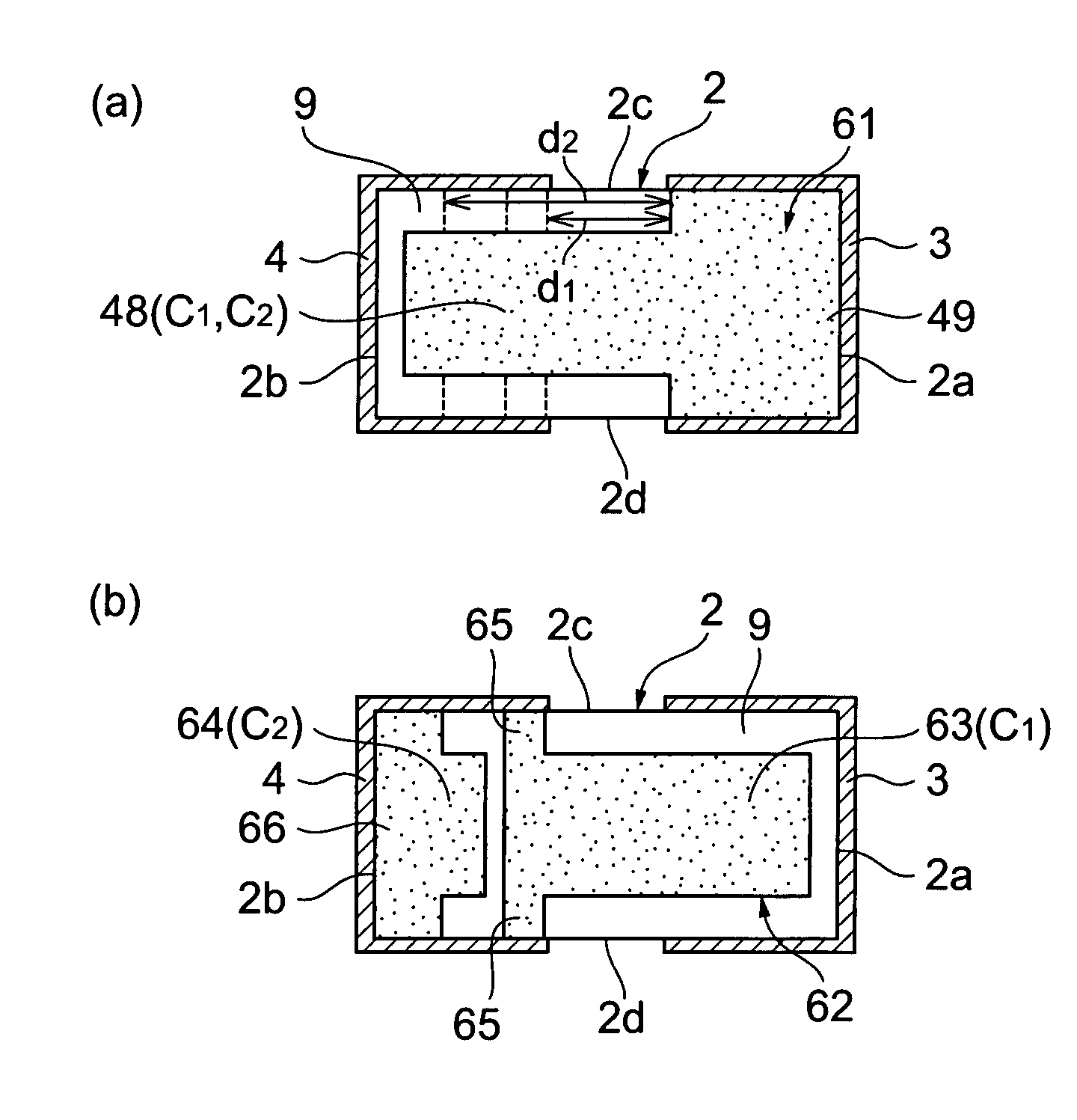
[0082]An internal electrode layer 61 is composed of an internal electrode 48 similar to that in the An internal electrode layer 62 is composed of internal electrodes 63, 64 formed alongside in the longitudinal direction of the laminate body 2. The internal electrode 63 has a pair of lead portions 65 led to the side faces 2c, 2d of the laminate body 2 and connected to the terminal electrode 4. The internal electrode 64 has a lead portion 66 led to the side faces 2c, 2d of the laminate body 2 and connected to the terminal electrode 4. The internal electrode 63 has an area larger than the internal electrode 64.
[0083]In the multilayer capacitor of this configuration, there are capacitor C1 and capacitor C2 formed. The capacitor C1 is composed of the internal electrodes 48, 63 of the mutually opposite polarities, and the dielectric layer 9 present between them. The capacitor C2 is composed of the internal electrodes 48, 64 of the mutually opposite polarities, and the dielectric layer 9 ...
PUM
| Property | Measurement | Unit |
|---|---|---|
| Area | aaaaa | aaaaa |
| Distance | aaaaa | aaaaa |
Abstract
Description
Claims
Application Information
 - Generate Ideas
- Intellectual Property
- Life Sciences
- Materials
- Tech Scout
- Unparalleled Data Quality
- Higher Quality Content
- 60% Fewer Hallucinations
Browse by: Latest US Patents, China's latest patents, Technical Efficacy Thesaurus, Application Domain, Technology Topic, Popular Technical Reports.
© 2025 PatSnap. All rights reserved.Legal|Privacy policy|Modern Slavery Act Transparency Statement|Sitemap|About US| Contact US: help@patsnap.com