Method and device for the combined representation of 2D fluoroscopic images and a static 3D image data set

a fluoroscopic image and data set technology, applied in image enhancement, instruments, angiography, etc., can solve the problem of 3d image data set overlaid with a dynamic 2d imag

Inactive Publication Date: 2008-07-24
SIEMENS HEALTHCARE GMBH
View PDF6 Cites 16 Cited by
  • Summary
  • Abstract
  • Description
  • Claims
  • Application Information

AI Technical Summary

Benefits of technology

[0016]The method according to the invention comprises the following steps: a) provision of a static 3D image data set of the heart, which has been recorded ECG-triggered at a first cardiac phase; b) acquisition, at even time intervals, of a series of 2D fluoroscopic images of the beating heart, an ECG of the beating heart being recorded during the acquisition and a cardiac phase being assigned to each fluoroscopic image; c) following acquisition of each fluoroscopic image, this fluoroscopic image being, if necessary, registered with the 3D image data set and a 2D pseudo-projection of the 3D image data set on to the image plane of the fluoroscopic image being calculated; d) representation of the series of fluoroscopic images consecutively on a screen, each fluoroscopic image being overlaid with the associated pseudo-projection. The method is characterized in that the pseudo-projection in step d) is represented differently or is not represented depending on the interval of the cardiac phase of the currently represented fluoroscopic image relative to the first cardiac phase. The pseudo-projection from the 3D image data set is thus not constant and statically blended but dynamically, depending on the cardiac phase of the fluoroscopic image currently being shown or its interval relative to the cardiac phase in which the 3D image volume was recorded. The visual impression of the combined representation can be improved by this means.
[0027]Besides the series of fluoroscopic images with the inventively overlaid pseudo-projection, a colored bar which, depending on the interval of the cardiac phase of the currently represented fluoroscopic image relative to the first cardiac phase, exhibits different colors or shades, is preferably also represented on the screen. This colored bar can be represented next to or in the overlaid image. The color coding indicates whether the current cardiac phase is located close to or further from the first cardiac phase. For example, green stands for the current cardiac phase being located in a predefined interval around the first cardiac phase and red for the current cardiac phase being located outside the predefined interval. This also makes it simpler for the doctor to find his / her way around the representation.

Problems solved by technology

The second problem is visualization of the 2D and 3D images registered with one another, i.e. the combined representation of fluoroscopic image and a corresponding projection of the 3D image data set.
The disadvantage is that a static 3D image data set is overlaid with a dynamic 2D image.

Method used


Image

  • Method and device for the combined representation of 2D fluoroscopic images and a static 3D image data set
  • Method and device for the combined representation of 2D fluoroscopic images and a static 3D image data set
  • Method and device for the combined representation of 2D fluoroscopic images and a static 3D image data set

Examples


Embodiment Construction

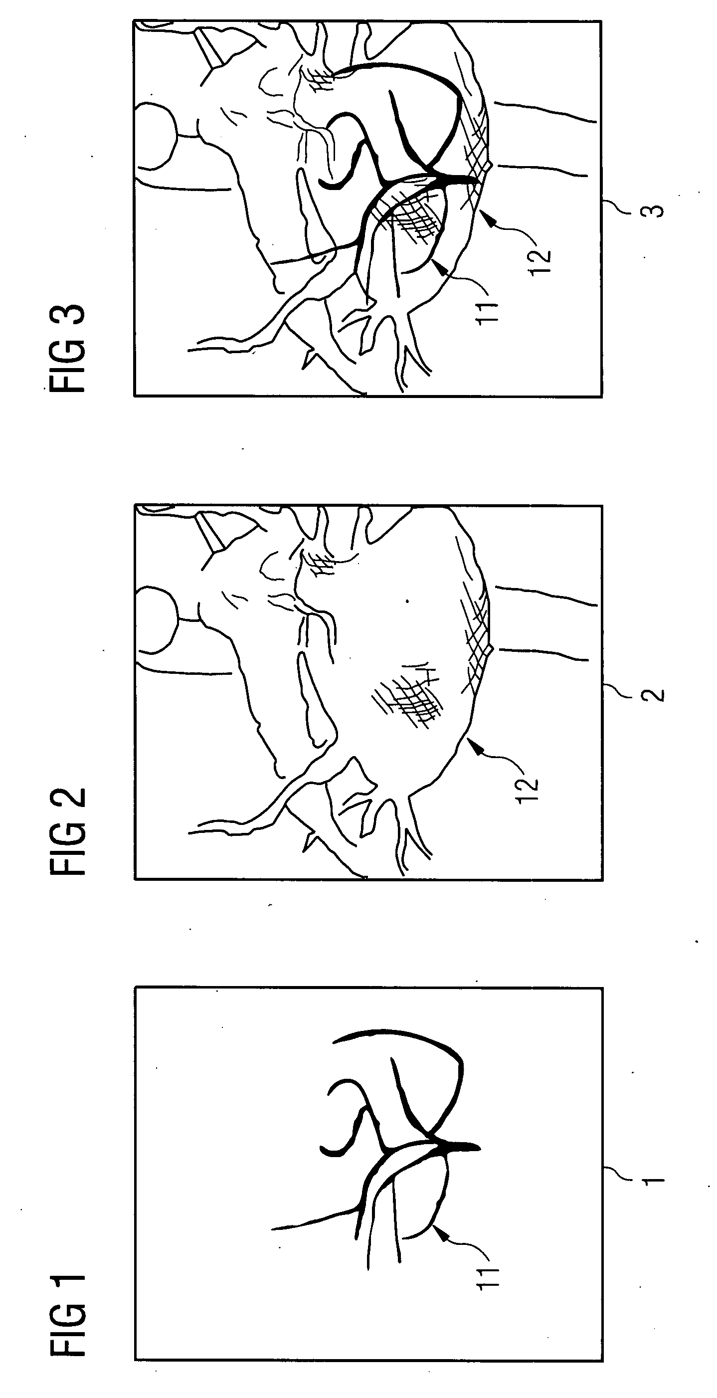
[0038]FIG. 1 shows in a simplified manner a fluoroscopic image 1 of the beating heart with a vascular tree 11. A good representation of a vascular tree 11 can in particular be achieved through the administration of contrast means. FIG. 1 reproduces only a single fluoroscopic image 1, whereas during an intervention in the heart a series of fluoroscopic images 1 comprising approximately 1-10, preferably 2-5, images per second, will typically be recorded. On this series of images, the vascular tree 11 would move accordingly with the heartbeat.

[0039]FIG. 2 shows the same object as FIG. 1, but in a different representation. FIG. 2 is actually designed to reproduce the impression of a pseudo-projection of a 3D image data set of the same heart obtained by means of rendering. The 3D image data set was produced e.g. by means of MR, CT or 3D rotational angiography and consequently exhibits spatial resolution and depth information. The heart 12 and some supplying vessels as well as the aorta c...


PUM


Abstract

The invention relates to a method and a device for the combined representation of a series of 2D fluoroscopic images of the beating heart with a static 3D image data set of the same heart. The fluoroscopic images are registered with the 3D image data set and from this a 2D pseudo-projection on to the image plane of each fluoroscopic image generated in each case. This is then represented with the associated fluoroscopic image overlaid. The method is characterized in that the pseudo-projection is represented differently in each case or is not represented depending on the interval of the cardiac phase of the currently represented fluoroscopic image relative to the cardiac phase of the 3D image data set.

Description

CROSS REFERENCE TO RELATED APPLICATIONS[0001]This application claims priority of German application No. 10 2006 046 733.7 filed Sep. 29, 2006, which is incorporated by reference herein in its entirety.FIELD OF THE INVENTION[0002]The invention relates to a method and a device for the combined representation of a series of consecutively recorded 2D fluoroscopic images of the beating heart with a static 3D image data set of the same heart.BACKGROUND OF THE INVENTION[0003]Minimally invasive interventions in the heart, e.g. catheter ablations and the placement of stents are nowadays generally controlled with the aid of fluoroscopic images. These are two-dimensional (2D) x-ray images recorded in real time, which are preferably obtained by means of special interventional C-arm x-ray devices. Being radioscopic images, the fluoroscopic images show no spatial-depth information, but they are available in real time and minimize the radiation loading for patient and doctor.[0004]The idea is alre...

Claims


Application Information

Patent Timeline
Patent Type & Authority Applications(United States)
IPC IPC(8): G06K9/00
CPCA61B6/032G06T2207/30101A61B6/466A61B6/503A61B6/504A61B6/5235A61B6/541G06T5/50G06T7/0012G06T7/0028G06T7/0038G06T2207/10072G06T2207/10121G06T2207/30048A61B6/463G06T7/33G06T7/38
Inventor JOHN, MATTHIASMEYER, ANDREASPFISTER, MARCUSRAHN, NORBERT
Owner SIEMENS HEALTHCARE GMBH
Why Eureka
Try Eureka