Light device including an outside bulb, especially a high pressure discharge lamp

a technology of discharge lamp and light device, which is applied in the direction of discharge tube luminescnet screen, electric discharge lamp, electrical apparatus, etc., can solve the problems of insufficient uv-blocking action of silica glass as the material for the outside bulb, residual transmission in the range of hard uv-c radiation, and restricted design freedom and/or limitation of the power output of the lamp, so as to achieve the effect of improving the white impression and targeting the influence of white light quality

Inactive Publication Date: 2006-12-14
SCHOTT AG
View PDF33 Cites 40 Cited by
  • Summary
  • Abstract
  • Description
  • Claims
  • Application Information

AI Technical Summary

Benefits of technology

[0033] Therefore, targeted influence over the quality of the white light can advantageously be exercised, when required. Provided the emission spectrum of the discharge body displays too much blue content, a targeted yellow self-coloring adjustment is also possible through the steepness of the UV-edge. This filters out excessive blue content. The yellow self-coloring compensates for the blue cast of the burner of the HID-lamp and in contrast to conventional HID-lamps an improved white impression is achieved.
[0034] The effect becomes all the more advantageous when temperature effects are considered additionally. Temperatures of between 600° C. and 850° C. or higher can occur on the inside wall of an HID-lamp that is close to the burner, causing the UV edge to be displaced toward lower energies.

Problems solved by technology

With respect to materials, the utilization of silica glass as the material for the outside bulb has the disadvantage of an insufficient UV-blocking action.
This however has the disadvantage of a residual transmission in the range of the hard UV-C radiation.
The utilization of soft glass in this context can lead to a restricted freedom in design and / or limitation of the power output of the lamp.
An additional problem of HID lamps in accordance with the current state of the art is the area of the leadthroughs.
The actual hermetic seal occurs here over only a few mm2 contact surface of Mo-foil with the surrounding glass and is therefore very unreliable.
The Mo-foil has a tendency to burn during sealing of the leadthrough.
During operation the fused in foils tend to oxidize.
This may result in leakages and failure of the lamp.
The thin foil permits only an insufficient energy transport into the lamp.
The production, or more precisely the multiple welding together of metal components is time consuming and expensive.
In addition, the dimensional expansion of the leadthrough system results in the overall length of the lamp becoming unfavorably large.
As mentioned previously, a disadvantage in WO 2004 / 077490 is that the material of the outside bulb is not specified.

Method used


Image

  • Light device including an outside bulb, especially a high pressure discharge lamp
  • Light device including an outside bulb, especially a high pressure discharge lamp
  • Light device including an outside bulb, especially a high pressure discharge lamp

Examples


Embodiment Construction

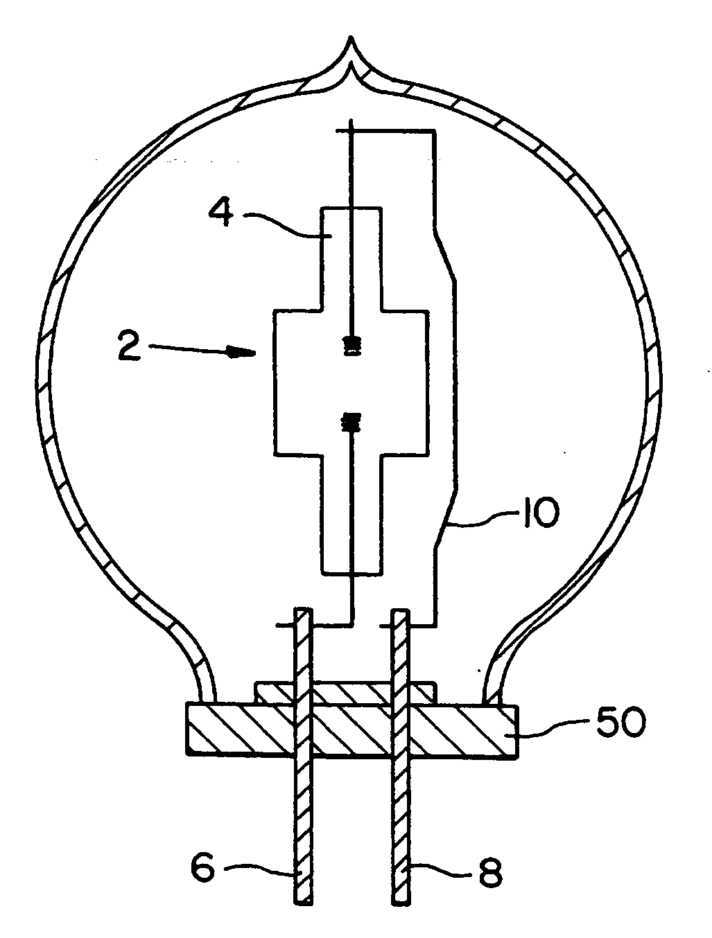
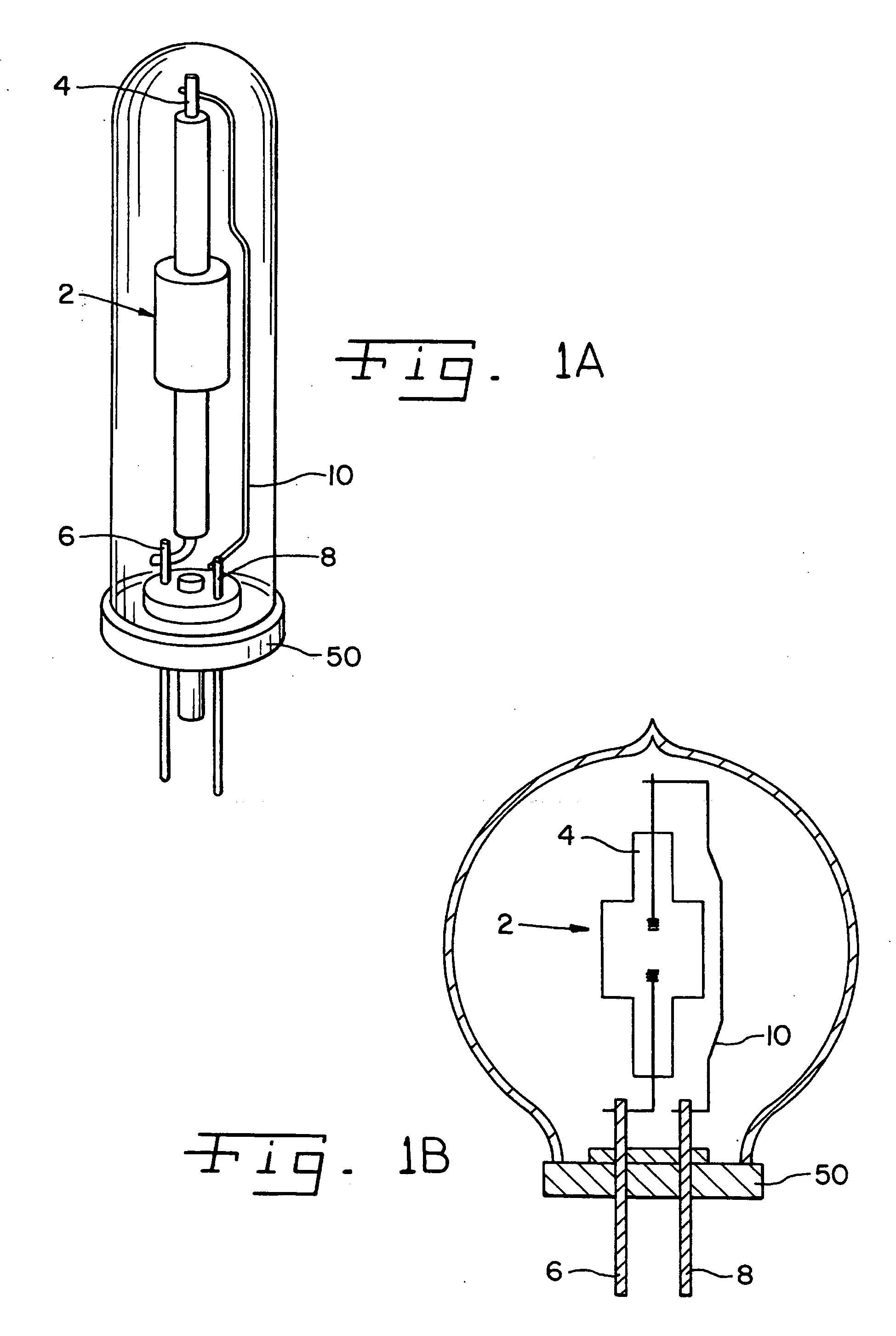
[0050] Referring now to the drawings, and more particularly to FIG. 1a, there is shown an HID-lamp, and FIG. 1b is an alternative design, with a leadthrough component as described, for example in WO 2004 / 077490, incorporated herein by reference.

[0051] In addition to the outside bulb 1, FIG. 1a also illustrates the burner system 2 which can be in the form of an Al2O3 burner. Burner system 2 is mounted on a nipple 4. The burner system includes a so-called first body which forms the discharge chamber of the burner. Nipple 4 results when the pump stem is flashed off after applying the vacuum that is present in the outside bulb. The so-called earlier fusing point then acts as the top fixed point of the burner system 2 which, in contrast for example to a W-spiral in a halogen lamp possesses clearly a greater mass, so that fastening in the outside bulb is advantageous. In addition, supply wires 6 and outlet wires 8 are shown. The supply wires and outlet wires 6, 8 are rigid enough to hold...


PUM

PropertyMeasurementUnit
weight %aaaaaaaaaa
weight %aaaaaaaaaa
pressureaaaaaaaaaa

Abstract

A light device, preferably a metal halide high pressure discharge lamp, which includes a first body which has a light element, a second body which encompasses the first body, whereby the second body consists essentially of an Al-silicate glass, for example a hard glass. The Al-silica glass has a Tg of >600° C., preferred >650° C., especially preferred >700° C., particularly preferred >750° C., and a thermal expansion coefficient α20/300>0, preferably in the range of 3≦α20/300≦6, particularly preferred 3.5≦α20/300≦5.5

Description

BACKGROUND OF THE INVENTION [0001] 1. Field of the Invention [0002] The present invention relates to a light device including at least one first body that includes a light element and a second body that encompasses the first body, and, more particularly, to high pressure discharge lamps and in particular to compact metal halide high pressure discharge lamps. [0003] 2. Description of the Related Art [0004] In high pressure discharge lamps a first body forms a sealed discharge chamber which is filled with a charge which can be ionized. The discharge chamber is also referred to as burner. The discharge chamber of high pressure discharge lamps as described for example in WO 2004 / 077490 or WO2005 / 033802 and includes one or several metal halides, mercury and rare-earth halides. These are put into the burner at room temperature (RT) in liquid or in solid form and following the ignition are then present in gaseous form due to the prevailing high pressures and temperatures. [0005] The second...

Claims


Application Information

Patent Timeline
Patent Type & Authority Applications(United States)
IPC IPC(8): H01J61/30H01J17/16H01J17/20
CPCC03C3/085C03C3/087C03C3/091H01J61/34C03C3/095H01J5/56H01J61/302C03C3/093
Inventor PEUCHERT, ULRICHZACHAU, THILOOTT, FRANZBRIX, PETERFECHNER, JOERG
Owner SCHOTT AG
Why Eureka
Try Eureka