Metal cutting system for effective coolant delivery

a cutting system and metal technology, applied in the direction of shaping cutters, cutting inserts, manufacturing tools, etc., can solve the problems of insufficient closeness, too far of a distance for effective cooling, and each variation has shown limited effectiveness, so as to achieve significant improvement in life

Active Publication Date: 2008-07-24
KENNAMETAL INC
View PDF99 Cites 69 Cited by
  • Summary
  • Abstract
  • Description
  • Claims
  • Application Information

AI Technical Summary

Benefits of technology

[0009]In one embodiment of the invention, the assembly comprises a tool holder having a recess to accept a cutting insert and a passage for coolant delivery; a shim having a cooling channel capable of delivering coolant to a flank face or cutting edge of an insert; a cutting insert having a frusto-conical depression in the center of the insert and an orifice aligned with the coolant passage of the tool holder; a top piece with a depression in a top surface and a frusto-conical bottom aligned with the frusto-conical depression of the cutting insert to form a fluid tight seal between the insert and top piece except for a rake face cooling channel spanning from the insert orifice to a

Problems solved by technology

This is too far of a distance for effective cooling.
Each variation has shown limited effectiveness.
Those with grooves between the top plate and the insert get fluid closer to the tool-workpiece interface but are not close enough.

Method used


Image

  • Metal cutting system for effective coolant delivery
  • Metal cutting system for effective coolant delivery
  • Metal cutting system for effective coolant delivery

Examples


Embodiment Construction

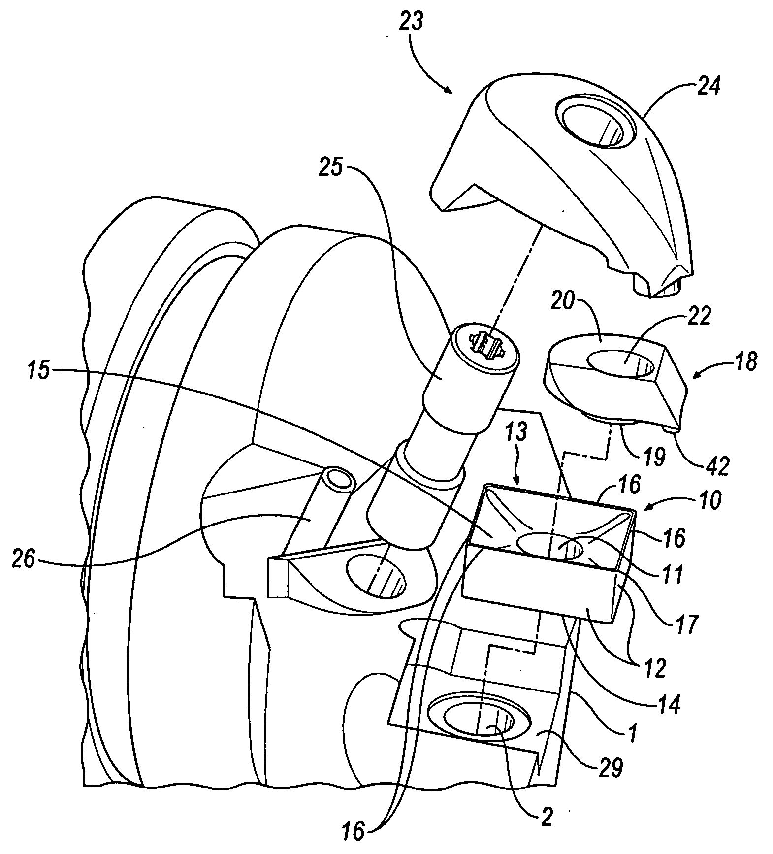
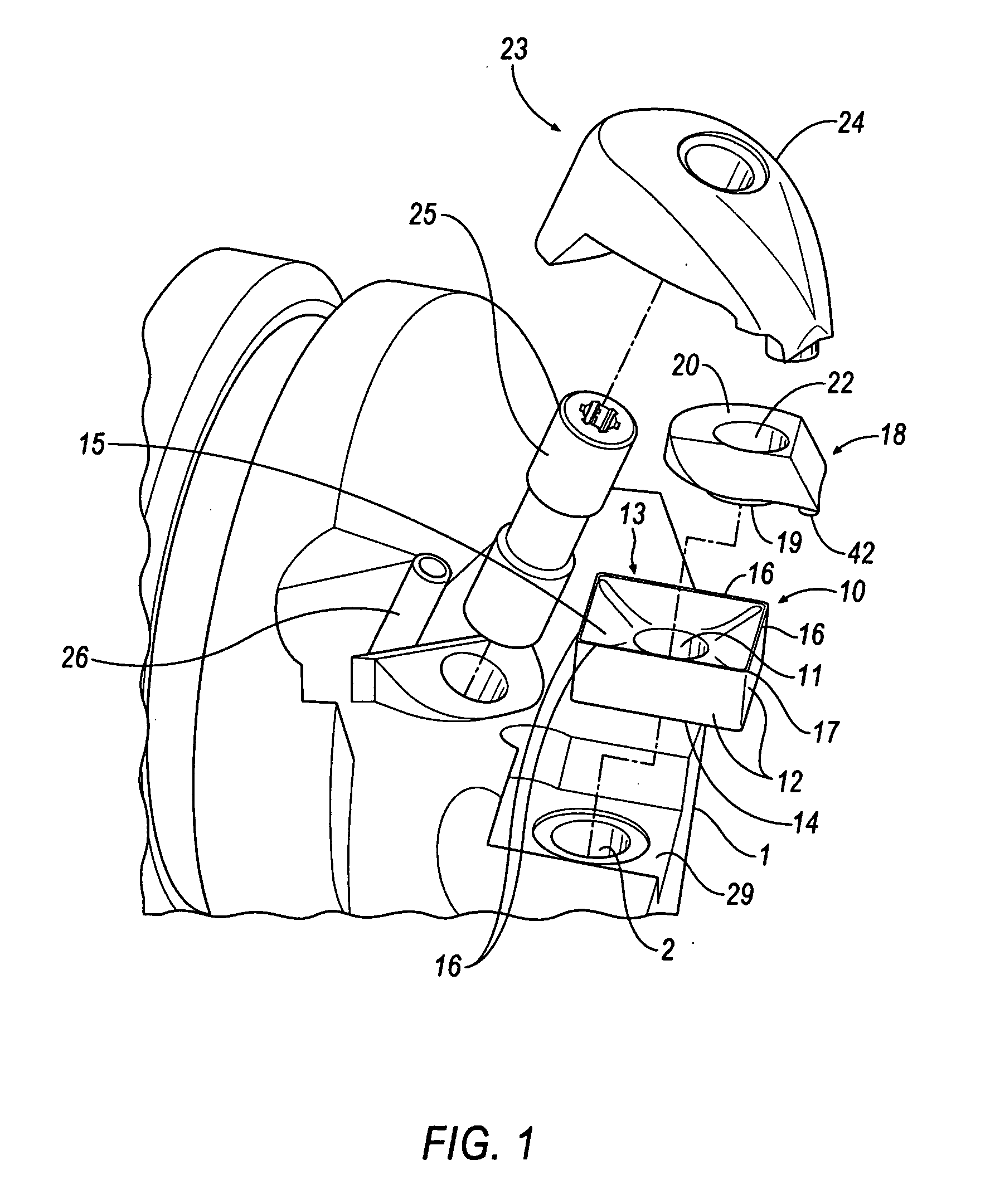
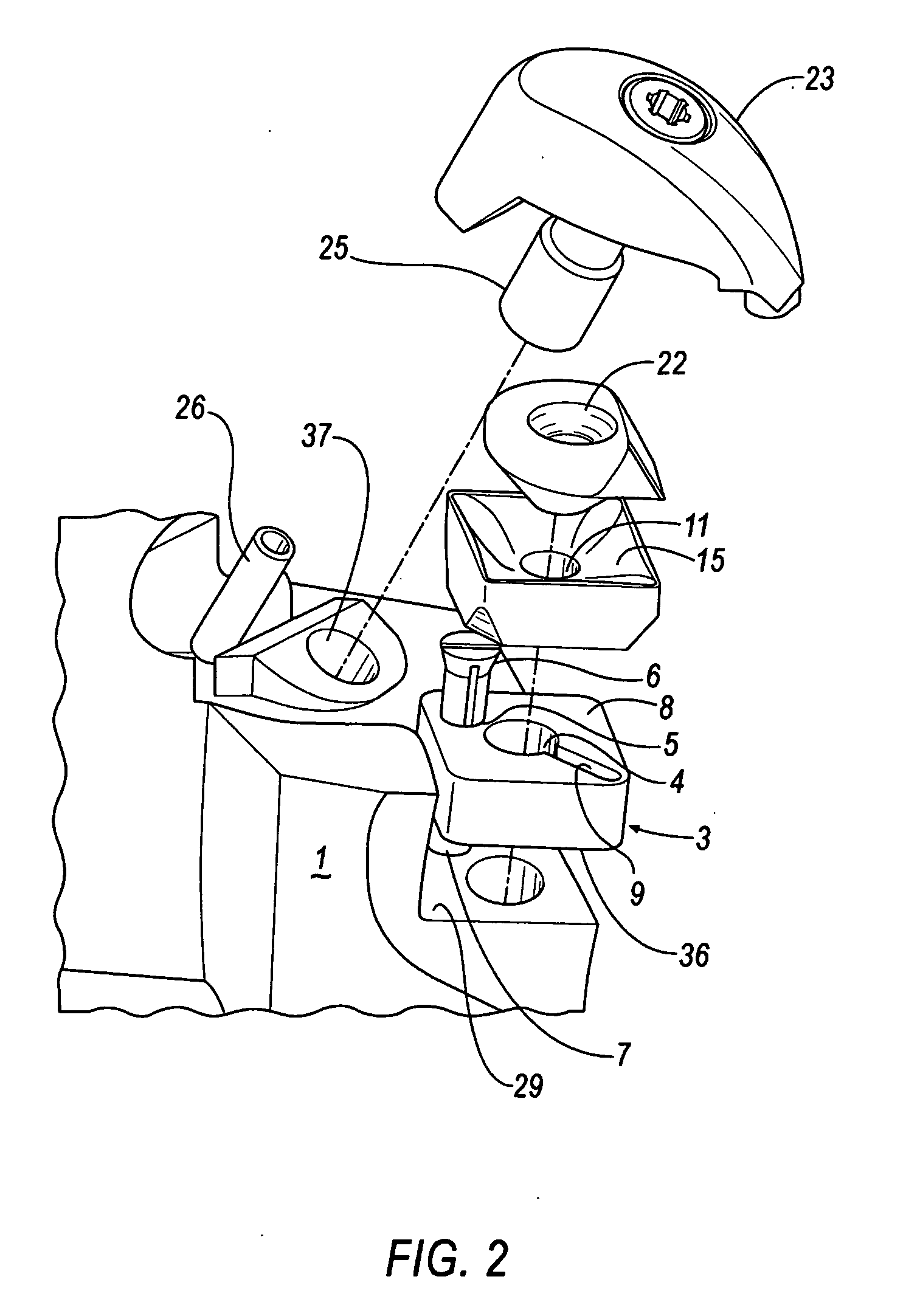
[0021]Referring to FIG. 1 of the invention, there is shown a tool holder 1 having a recess 29 for receiving a cutting insert 10. The tool holder 1 also has a coolant passage 2 for delivering fluid coolant to the recess 29. An indexable, cutting insert 10 is positioned in the recess 29. The cutting insert 10 has at least one flank face 12, a rake face 13 and a bottom face 14. The intersection between the flank face 12 and the rake face 13 forms a cutting edge 16. In the instance of a plurality of flank faces, the intersection between two adjacent flank faces 12 and the rake face 13 forms a cutting corner 17. It will be appreciated that a round cutting insert does not include two adjacent flank faces and therefore does not include a cutting corner. Although a round cutting insert does not include a cutting corner it will be appreciated that in any case, a cutting edge is present. An insert depression 15 is located in the rake face 13 of the insert 10. The insert depression 15 is an ar...


PUM

PropertyMeasurementUnit
Lengthaaaaaaaaaa

Abstract

A metal cutting system with a tool holder, a shim, an insert with a top depression, a top piece and a clamp. A rake face cooling channel for fluid delivery is formed between the top piece and the depression in the insert. A primary discharge slot at the end of the rake face cooling channel delivers fluid from below the cutting edge of the insert. A second cooling channel for delivery of fluid to the flank face is formed between the insert and the shim or is formed between the shim and the tool holder with a portion of the cooling channel passing through the shim.

Description

BACKGROUND OF THE INVENTION[0001]1. Field of the Invention[0002]The subject invention is directed to metal cutting system and, in particular, to a metal cutting system adapted to permit effective coolant delivery to an interface between a metal cutting tool and a workpiece.[0003]2. Background of the Invention[0004]Metal cutting tools for performing metal working operations generally comprise a cutting insert having a surface terminating at a cutting edge and a tool holder formed with a seat adapted to receive the insert. The cutting insert engages a workpiece and removes a chip therefrom. Obviously, it is desirable to lengthen the life of a cutting insert in metal cutting operations. Longer insert life leads to lower operating costs and better machine efficiency. One factor in the life of a cutting insert is the temperature of the insert during cutting operations. A higher insert temperature will result in a shorter useful life of an insert.[0005]3. Description of the Related Art[00...

Claims


Application Information

Patent Timeline
IPC IPC(8): B23P15/28
CPCB23B27/10B23B27/164B23B2205/16Y10T407/14Y10T407/24Y10T407/118Y10T407/2282Y10T407/11Y10T408/44
Inventor PRICHARD, PAUL D.ANDRAS, LINN R.
Owner KENNAMETAL INC
Why Eureka
Try Eureka