Method of manufacturing display unit

Inactive Publication Date: 2008-07-24
PANASONIC LIQUID CRYSTAL DISPLAY CO LTD +1
2 Cites 0 Cited by

AI-Extracted Technical Summary

Problems solved by technology

Consequently it has become impossible to ignore panel deformation such as that which occurs with shrinkage due to the effect of heat in the course of manufacture, for example.
Since the transistors and the circuits do not easily transmit light, they are thus often arranged around the pixels.
Here, when overlaying accuracy or processing accuracy of the TFT panel or the CF panel is not enough, then the pixel parts of the TFT panel overlaps the BM part of the CF panel, and a good aperture rate cannot be obtained.
Accordingly, repeated exposures of many layers cause a mechanical error or a position measurement error at the time of alignment in each layer, so that the degree of deformation of each pattern shape generally tends to increase.
As the deforma...

Method used

[0046]By this operation, each time a layer is laid over another, a pattern in the upper layer approaches the arrangement of the pattern in the reference layer. As a result, it is possible to reduce deviation in arrangements of surface patterns among a plurality of produced panels.
[0059]Next, the controller 104 calculates and records correction parameters (referred to as alignment correction parameters) to be applied to the drawing pattern obtained in S103, in order to minimize the alignment error between the drawing pattern and the substrate 310 (S104).
[0072]The transition diagram show...

Benefits of technology

[0010]To solve the above problem, the present invention provides an exposur...

Abstract

An exposure method that suppresses distribution of pattern shapes at the time of exposure.
In a manufacturing method for a display unit, a layer forming a reference for pattern arrangement is determined among layers formed on a panel. An arrangement of a pattern in a layer above the reference layer is determined using a value obtained from distribution of the pattern arrangement in the reference layer.

Application Domain

Technology Topic

Image

  • Method of manufacturing display unit
  • Method of manufacturing display unit
  • Method of manufacturing display unit

Examples

  • Experimental program(2)

Example

VARIATION EMBODIMENT 1
[0098]Next will be described an embodiment in which the asymptotic alignment method is applied to a manufacturing process of a CF panel. The idea of modifying drawing patterns in manufacturing a CF panel is similar to the method of modifying drawing patterns in the TFT panel manufacturing process shown in FIG. 5.
[0099]However, as shown in FIG. 9, generally a manufacturing process 901 of a TFT panel and a manufacturing process 902 of a CF panel are separate processes, and overlaying process 903 is performed thereafter. This requires a means 904 for transferring the center of distribution of the reference layer for pattern alignment in the TFT panel manufacturing process 901 to the CF panel manufacturing process 902.
[0100]In detail, the controller 104 comprises a storage unit that has a first storage area for storing a reference value used in the TFT panel manufacturing process 901 and a second storage area for storing a reference value used in the CF panel manufacturing process 902. The controller 104 stores the center of distribution of the layer as the reference in the TFT panel manufacturing process 901 in the first storage area. In other words, the controller 104 stores a scaling ratio of a drawing pattern used for pattern formation in the uppermost layer in the TFT panel manufacturing process 901, with respect to the original drawing pattern. In the CF panel manufacturing process 902, the controller 104 transfers the value stored in the first storage area to the second storage area.
[0101]Then, in the CF panel manufacturing process 902, the controller 104 uses the value stored in the second storage area, as the reference value. That is, the controller 104 modifies the original drawing pattern for the BS layer in the case of no panel shrinkage, by multiplying it by the reference value (scaling ratio). Then, the controller 104 uses the modified drawing pattern to form the BS layer.
[0102]FIG. 10 illustrates a TFT panel 1110 in which a substrate layer 1111, a layer A, and a layer B have been formed. As shown in the figure, respective alignment marks 1112, 1115 and 1116 in these layers overlap each other.
[0103]A pattern in the CF panel is formed such that the center of distribution 1122 of the alignment mark 1121 in the BM layer 1120 coincides with the center of distribution 1114 of the distribution 1113 of the substrate layer 1111 in the TFT panel manufacture process. Since the drawing pattern in the BM layer 1120 is performed on the basis of the center of distribution, the misalignment amount between the BM layer 1120 and the layer B can be reduced. Thus, a margin of alignment between the BM layer and the layer B can be improved.

Example

VARIATION EMBODIMENT 2
[0104]The asymptotic alignment method can be applied to an exposure method using a mask.
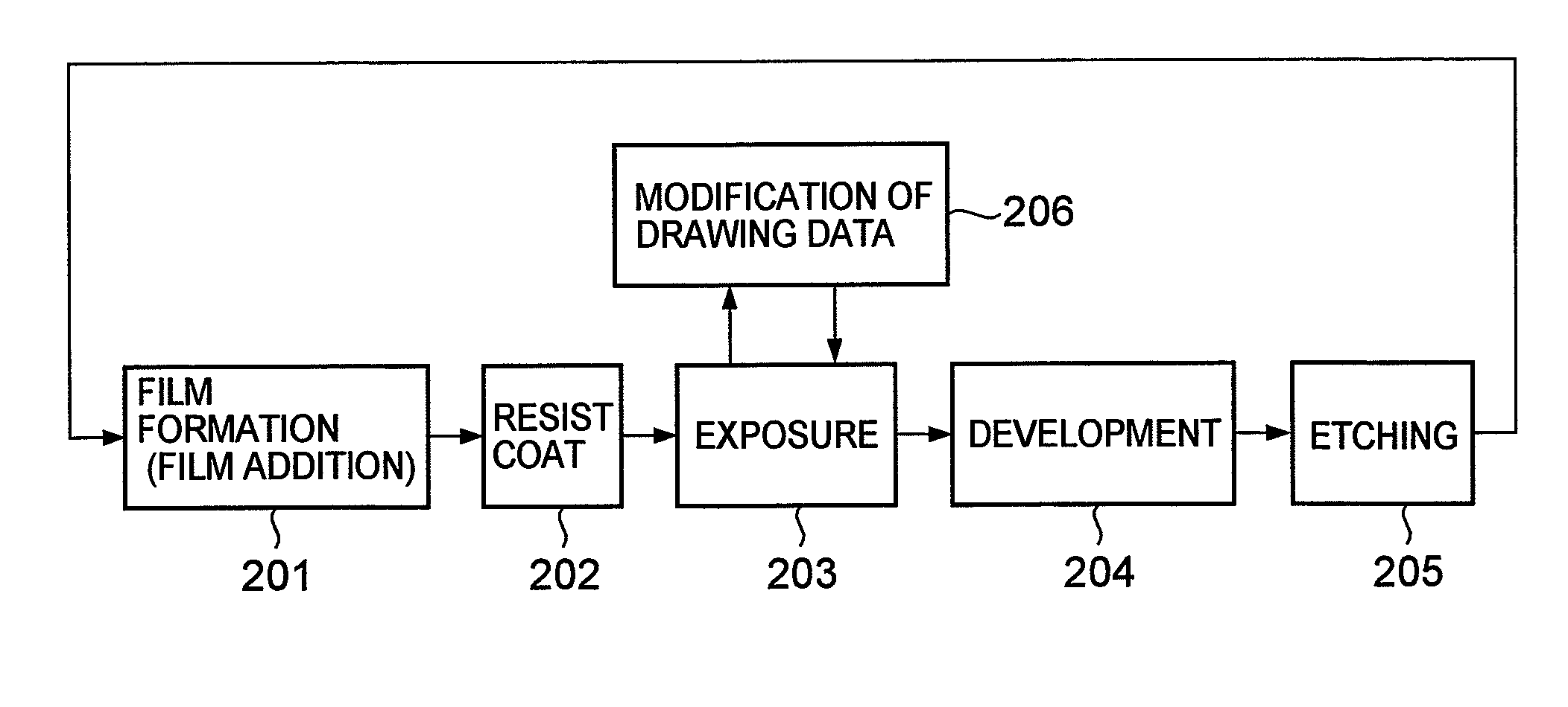
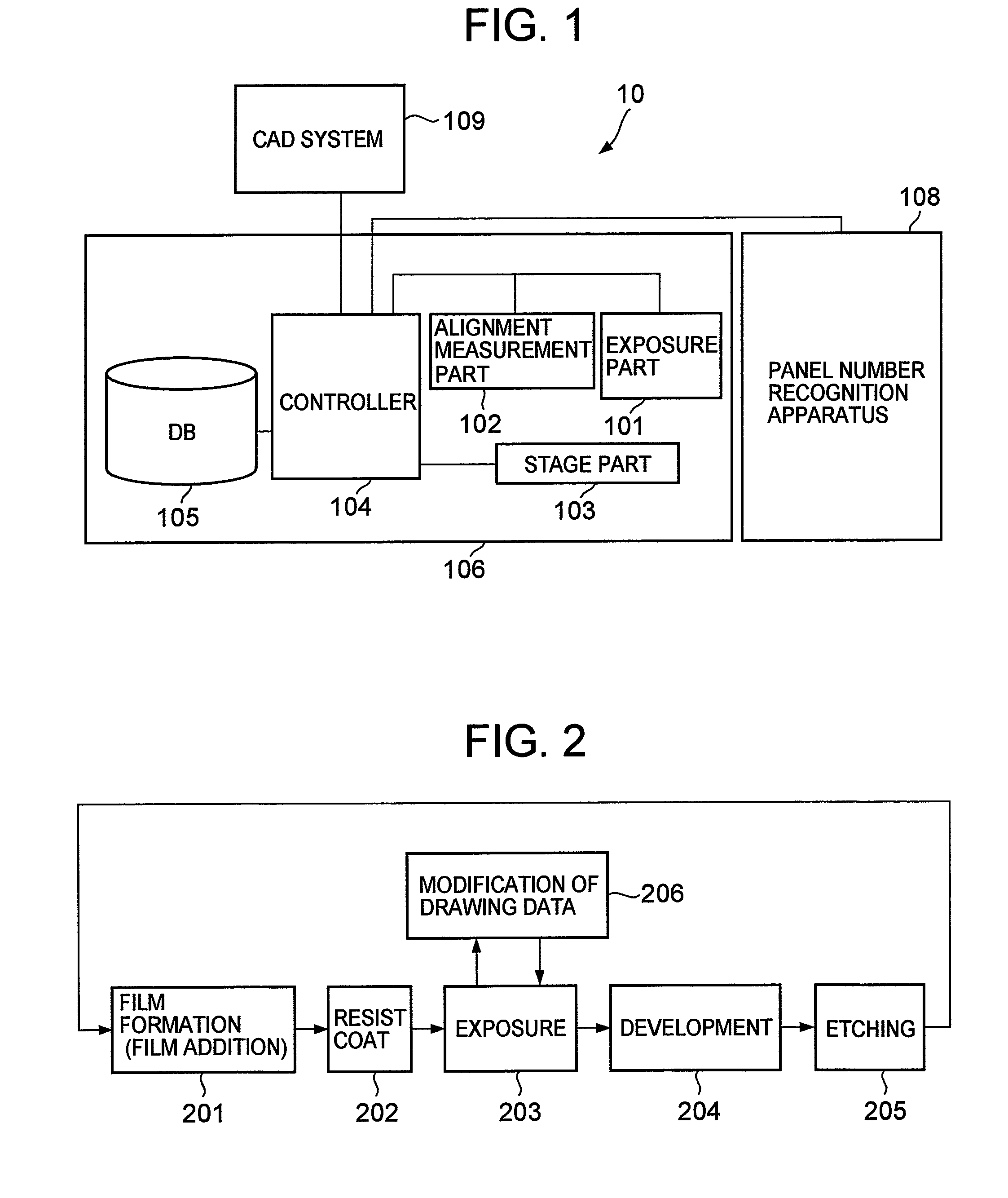
[0105]FIG. 11 shows processing flow in such a case. The processing flow shown in the figure is almost the same as that shown in FIG. 5. However, although a drawing pattern in the direct exposure method forms data for exposure and can be easily modified, a mask used for exposure cannot be modified. Accordingly, an alignment position of a mask is adjusted at the time of exposure, to form a desired pattern.
[0106]To that end, instead of the above-described processing in S202, the controller 104 obtains a mask alignment position for achieving the reference value (scaling ratio) calculated and stored in the statistic database 503. Furthermore, the controller 104 obtains a scaling ratio of the pattern formed at that alignment position, with respect to the pattern formed in the case where mask exposure is performed at the original alignment position. The obtained scaling ratio is stored in the drawing database 501. A relation between the scaling ratio and the mask alignment position is determined in advance.
[0107]Accordingly, the drawing database 501 stores, instead of data of a drawing pattern, a number of a mask used, a mask alignment position, and a scaling ratio of a pattern to be formed (a scaling ratio of a pattern formed by exposure at the mask alignment position, to the pattern formed by exposure at the original alignment position) for each exposure process number.
[0108]In S103, the controller 104 obtains the mask number and the mask alignment position corresponding to the exposure process number set in S101. The controller 104 obtains an arrangement misalignment between the already-formed pattern in the substrate layer (reference layer) and a pattern to be formed at the obtained mask alignment position.
[0109]Further, in S107, the controller 104 modifies the mask alignment position according to the alignment correction parameters, and performs mask exposure at the modified mask alignment position. That is, the controller 104 multiplies “the scaling ratio at the original alignment position” obtained in S103 by “the scaling ratio in the alignment correction parameters” calculated in S106, to obtain “the scaling ratio of the drawing pattern to the drawing pattern at the original alignment position”. Thus, the controller 104 determines the mask alignment position such that the pattern of the obtained scaling ratio can be formed, and performs exposure.
[0110]Several embodiments have been described above.
[0111]According to the above embodiments, it is possible to reduce distribution in shapes of a TFT panel. As a result, leeway in design margin is produced. Furthermore, since leeway is also realized in manufacturing margin, improvement in yield can be anticipated, leading to cost reduction.
[0112]The present invention is not limited to the above embodiments, and various modifications are possible.
[0113]For example, size and shape of panels may be recognized by using an inspection apparatus other than exposure equipment.
[0114]Further, the above embodiments are applied to the manufacture of a liquid crystal display unit. However, the present invention can be applied to processing of other display units, printed circuit boards, semiconductor devices, and the like, in which panel deformation affects processing accuracy.
[0115]A panel includes a print circuit board, a panel of a display unit, a semiconductor wafer and the like.

PUM

no PUM

Description & Claims & Application Information

We can also present the details of the Description, Claims and Application information to help users get a comprehensive understanding of the technical details of the patent, such as background art, summary of invention, brief description of drawings, description of embodiments, and other original content. On the other hand, users can also determine the specific scope of protection of the technology through the list of claims; as well as understand the changes in the life cycle of the technology with the presentation of the patent timeline. Login to view more.

Similar technology patents

Classification and recommendation of technical efficacy words

Why Eureka
Try Eureka