
Miniature fiber optic spectroscopy probes

a fiber optic spectroscopy and probe technology, applied in the direction of spectroscopy diagnostics, printers, instruments, etc., can solve the problems of large size limitation, expensive processing, and complex design described

Inactive Publication Date: 2008-07-24
PRESCIENT MEDICAL
View PDF12 Cites 17 Cited by
  • Summary
  • Abstract
  • Description
  • Claims
  • Application Information

AI Technical Summary

Problems solved by technology

The designs described are rather complex and require expensive processing.
In addition, they are still rather size limited by the particular ring-center and paired fiber configurations.

Method used


Image

  • Miniature fiber optic spectroscopy probes
  • Miniature fiber optic spectroscopy probes
  • Miniature fiber optic spectroscopy probes

Examples


Embodiment Construction

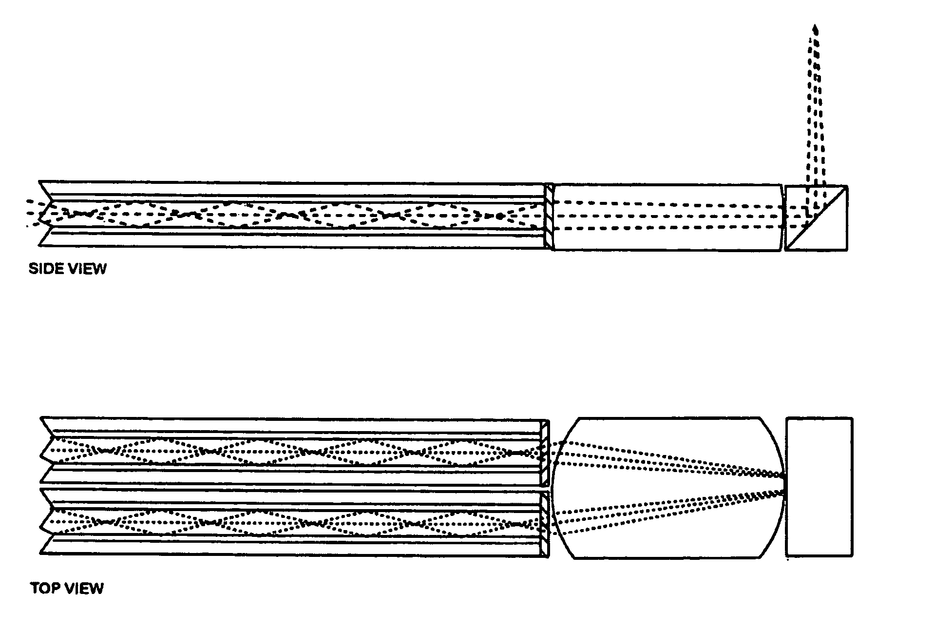
[0042]The invention provides various fiber optic probe assemblies for the delivery and collection of light in small spaces. The provided probe assemblies are small, flexible and well suited to performing minimally invasive spectroscopic examinations of biological tissues in-vivo. The invention also provides intravascular catheters that include the fiber optic probe assemblies.

[0043]The invention is described below with reference to the appended figures.

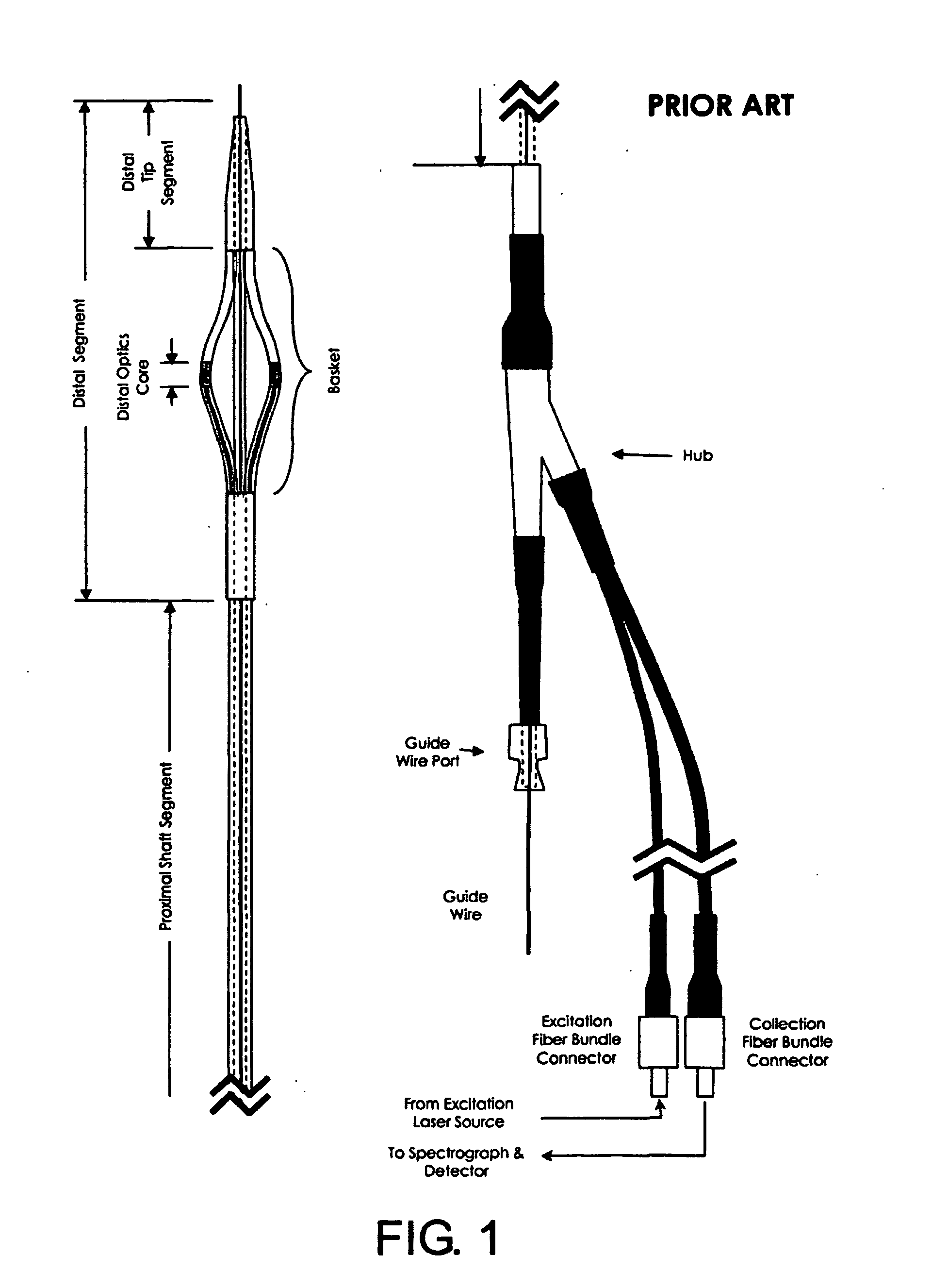
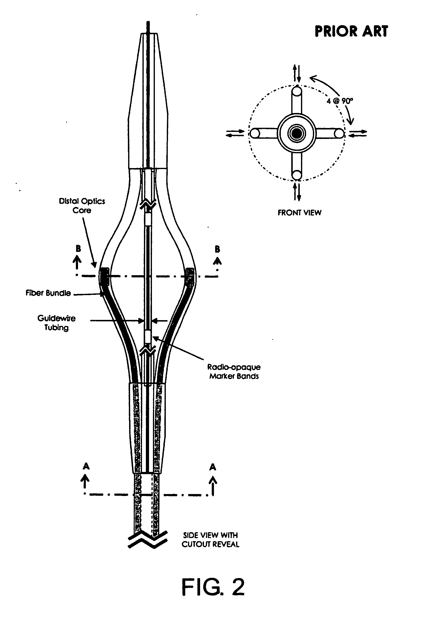
[0044]A 4-channel basket catheter profile is shown in FIGS. 1 and 2. This particular configuration is an “over the wire” catheter with a guidewire lumen passing the entire length of the catheter, and out through the “guide wire port” on the hub. The fiber bundles begin within each distal optics core and extend to the proximally to the connectors. FIG. 1 shows the proximal hub and connections used for manipulation and connecting the fibers to a laser source and spectrometer for signal analysis. FIG. 2 shows further details with respect...


PUM


Abstract

The invention provides various fiber optic probe assemblies for the delivery and collection of light in small spaces. The provided probe assemblies are small, flexible and well suited to performing minimally invasive spectroscopic examinations of biological tissues in-vivo. The invention also provides intravascular catheters that include the fiber optic probe assemblies.

Description

[0001]This application claims the benefit of U.S. provisional patent application Ser. No. 60 / 812,594 filed Jun. 12, 2006, which is incorporated by reference herein in its entirety.FIELD OF THE INVENTION[0002]The invention relates to the fields of side-viewing fiber optic probes and catheter-based optical diagnostics.BACKGROUND OF INVENTION[0003]Collection efficiency is a measure of the total light collecting capability of an optical probe. It is generally computed from the total collection fiber core area, numerical aperture (NA) and aim relative to the desired source. Numerical aperture is driven by various material constraints within the fiber and available for miniature lenses and prisms. Lens shape also effects both the direction and effective aperture for collection. For most spectroscopy applications, constraints on the miniaturization of the probe design are primarily driven by two opposing attributes: high collection efficiency and a small profile.[0004]Existing fiber optic ...

Claims


Application Information

Patent Timeline
Patent Type & Authority Applications(United States)
IPC IPC(8): A61B1/06
CPCA61B5/0066A61B5/0075A61B5/0084G02B6/4416G01N21/65G01N2021/656G02B6/32A61B5/6858
Inventor FURNISH, SIMON M.
Owner PRESCIENT MEDICAL
Learn More