Mis patellar preparation
a patellar and mis technology, applied in the field of minimally invasive equipment, can solve the problems of not being able to prepare and implant the entire patella, not being able to secure the prosthetic patella, and not having a system that allows the preparation and implantation of the entire patella, so as to achieve less strain on the patella and quadriceps tendon
- Summary
- Abstract
- Description
- Claims
- Application Information
AI Technical Summary
Benefits of technology
Problems solved by technology
Method used
Image
Examples
embodiment 300
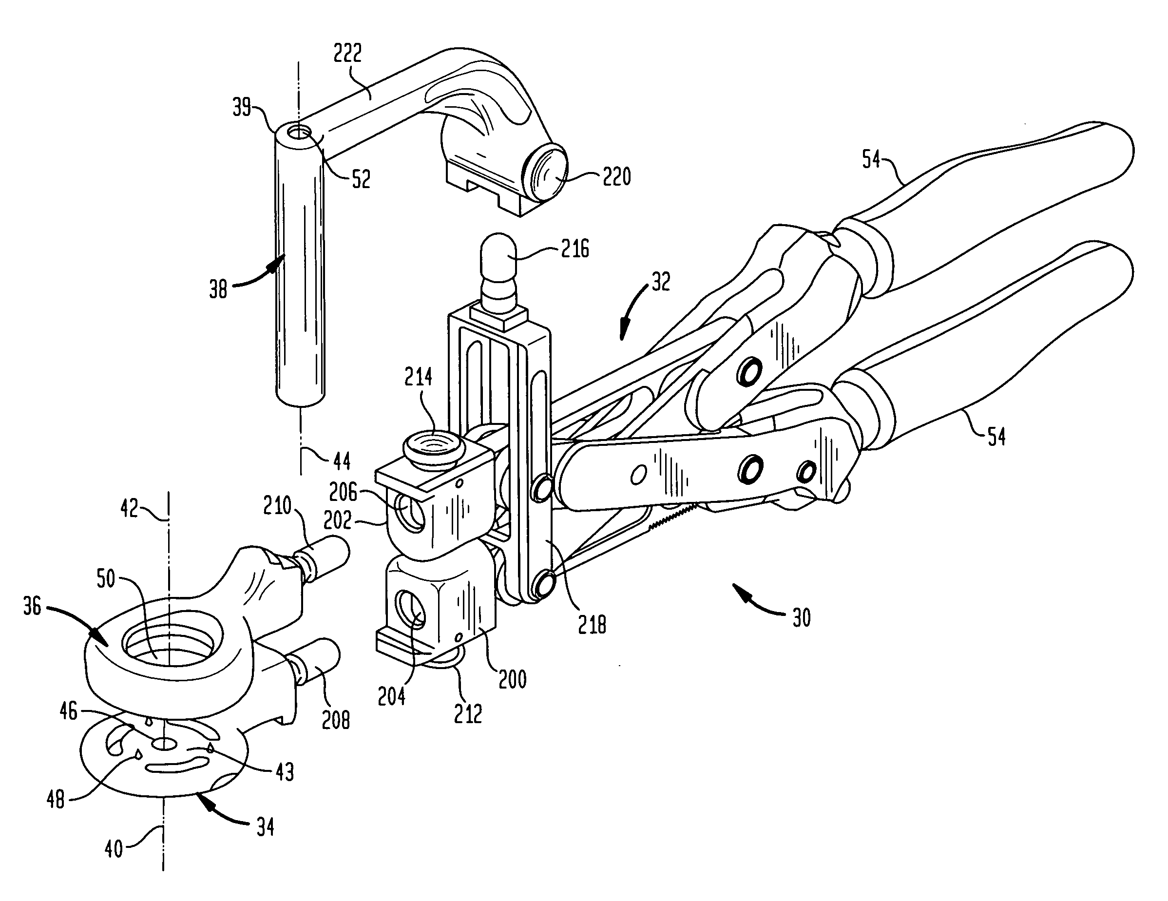
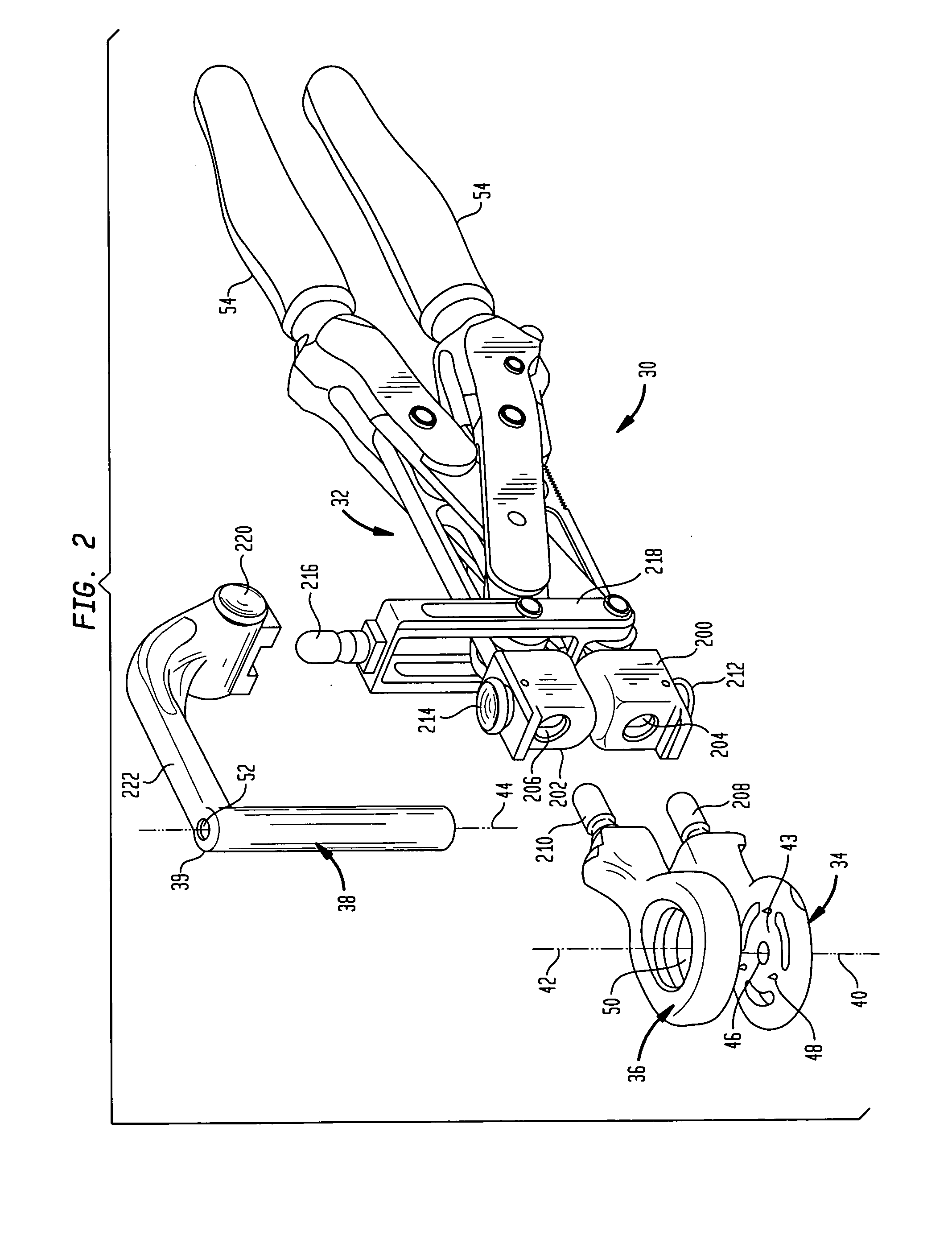
[0070]Referring to FIG. 25A there is shown an exploded view of an additional embodiment which is generally denoted as 300. The embodiment 300 includes a drive shaft 302 coupled to a ball joint generally denoted as 304 coupled to a worm gear shaft 306. Worm gear shaft extends through an opening 308 of worm gear 310 which fits inside housing 312. Housing 312 includes an axle 314 in which a drive pinion 316 is mounted. Drive pinion 316 is operatively connected to reamer 318 which has a face 320 for engaging the posterior surface of the patella. The guide shaft 322 extends through the patella (not shown) as do the guide and drive shafts previously described, for example shaft 70. An attachment element 324 is fixed to housing 312 so that the reaming system 300 may be attached to the clamping handle of FIG. 2. The U-joints and drive shaft are coupled to the respective gear and U-joint portions by typical pins 326 for the transmission of the drive torque.
[0071]Referring to FIGS. 25B and 25...
embodiment 400
[0072]Referring to FIGS. 26A and 26B there is shown yet a further alternate embodiment generally denoted as 400 which is in the form of a rack and pinion system. Embodiment 400 includes rack 402 and pinion 404 again mounted in a housing 412 including an axle 314 to which pinion 404 is fixedly attached. Again housing 412 includes attachment coupling element 424 for coupling the drive system 400 to the handle of FIG. 2. Although the reamer is not shown in FIGS. 26 and 26B it is fixedly coupled to pinion 404 for rotation therewith. obviously a drive system would be used to reciprocating rack 402 which in turn would rotate pinion 404 first in one direction and then in the other direction which in turn drives the reamer which resects the posterior surface of the patella as described hereinbefore.
PUM
 Abstract
Description
Claims
Application Information
 - R&D
- Intellectual Property
- Life Sciences
- Materials
- Tech Scout
- Unparalleled Data Quality
- Higher Quality Content
- 60% Fewer Hallucinations
Browse by: Latest US Patents, China's latest patents, Technical Efficacy Thesaurus, Application Domain, Technology Topic, Popular Technical Reports.
© 2025 PatSnap. All rights reserved.Legal|Privacy policy|Modern Slavery Act Transparency Statement|Sitemap|About US| Contact US: help@patsnap.com


