Device, method and program for soldering

a technology of soldering device and program, which is applied in the direction of instruments, lighting and heating apparatus, furnaces, etc., can solve the problems of large fluctuation of temperature in the furnace, delay in heating the furnace, and breakdown of low heat resistance components mounted on the substrate, etc., to achieve the effect of improving the stability of temperatur

Inactive Publication Date: 2008-07-24
TAMURA KK +1
View PDF12 Cites 5 Cited by
  • Summary
  • Abstract
  • Description
  • Claims
  • Application Information

AI Technical Summary

Benefits of technology

[0022]According to the present invention, the temperature of the object zone is controlled while taking into account the heat capacity of the heated object together with the initial temperature in the temperature control of the object zone where the heated object is processed with heat. This enables to improve the stability of the temperature in the object zone.

Problems solved by technology

However, Patent Document 1 does not take into account that a substrate deprives a part of the heat capacity of the furnace if the temperature of the furnace is controlled after the temperature has drastically dropped, so the fluctuation of temperature in the furnace becomes large.
Therefore, a component of low heat resistance mounted on the substrate may be broken due to the temperature fluctuation inside the furnace.
Further, in Patent Document 1, the time to heat the furnace delays.
However, as in the case of Patent Document 1, the temperature in a furnace when a substrate is carried into the furnace is not adjusted in Patent Document 2.
Therefore, there is a limit in suppressing drastic fluctuation of the temperature in the furnace.

Method used


Image

  • Device, method and program for soldering
  • Device, method and program for soldering
  • Device, method and program for soldering

Examples


Embodiment Construction

[0029]Hereinafter, an embodiment of the present invention will be described according to the drawings.

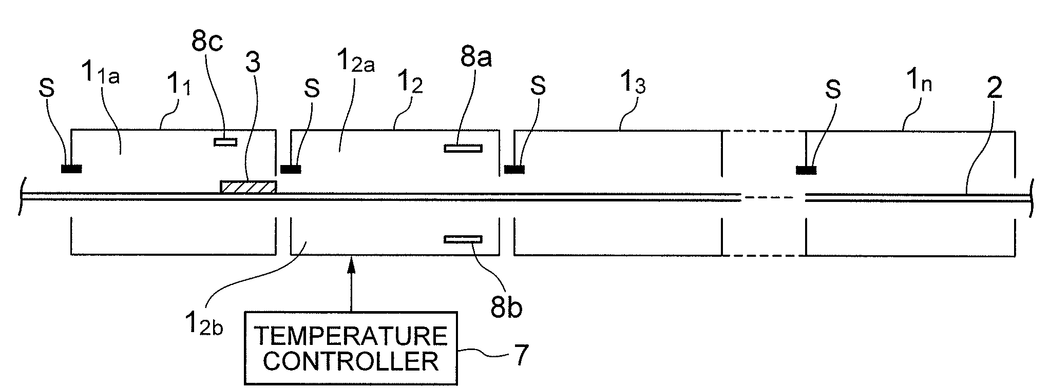
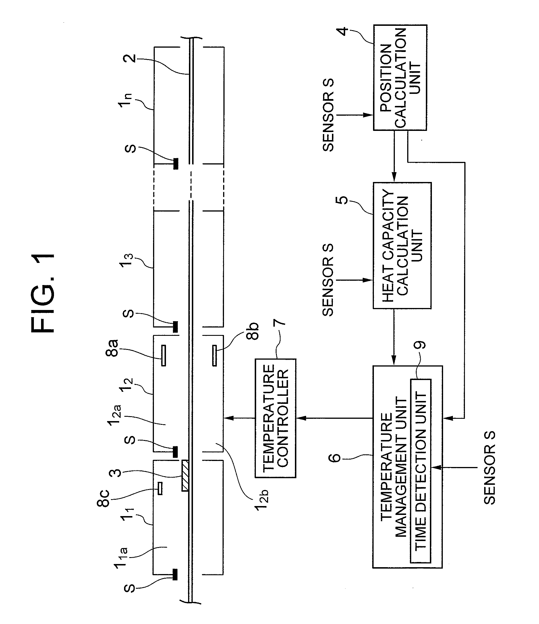
[0030]First, the difference between the present embodiment and the art disclosed in Patent Documents 1 and 2 will be clarified. As shown in FIG. 1, a soldering device includes a plurality of zones 11, 12, 13, . . . 1n which communicate with each other. The zones 11, 12, 13, . . . 1n may be configured such that they are arranged in one furnace while being partitioned from each other, or each of them is formed of an independent furnace. In the case that each of the zones 11, 12, 13, . . . 1n is formed of an independent furnace, it is desirable that the connecting part between adjacent furnaces is isolated from the atmosphere so that the temperature in the furnaces will not be affected by the atmospheric temperature. It should be noted that the number of zones 11, 12, 13, . . . 1n which communicate with each other is not limited to that shown in FIG. 1, and it may vary according to pro...


PUM

PropertyMeasurementUnit
heat capacity calculationaaaaaaaaaa
heat capacityaaaaaaaaaa
temperatureaaaaaaaaaa

Abstract

Soldering can be performed in a state where the temperature in an object zone is stable, regardless of the heat capacity of a soldering object. A soldering device includes: a position calculation unit which calculates the position of a heated object according to operational information of a conveyer which sequentially transfers the heated object into a plurality of zones for heat processing communicated with each other; a heat capacity calculation unit which calculates the heat capacity of the heated object; and a temperature management unit which controls the temperature in an object zone into which the heated object is carried, upon receiving positional information from the position calculation unit. The temperature management unit feedforward-controls the temperature in the object zone by adjusting the heat capacity of the object zone according to the heat capacity calculated by the heat capacity calculation unit.

Description

BACKGROUND OF THE INVENTION[0001]1. Field of the Invention[0002]The present invention relates to a device, a method, and a program for soldering a soldering object while transferring it into a plurality of zones for processing.[0003]2. Related Art[0004]A method of soldering a soldering object while transferring it into a plurality of zones for processing has been adopted. In order to perform this kind of soldering, it is necessary to detect the position of a substrate which is a soldering object and the temperature of the subject at the position, and to control the temperature to which the substrate is heated according to the detected information.[0005]Japanese Patent Application Laid-Open No. 1-147281 (Patent Document 1) discloses art which is a so-called feedback control, in which a substrate arrival sensor detects that a substrate arrives at a predetermined position, a temperature sensor detects the temperature of the substrate which arrives at the predetermined position, and the...

Claims


Application Information

Patent Timeline
Patent Type & Authority Applications(United States)
IPC IPC(8): G06F19/00B23K1/00B23K1/008B23K3/04B23K31/02H05K3/34
CPCB23K1/008
Inventor YAMAGUCHI, TAKAHITODOHZONO, KIYOSHI
Owner TAMURA KK
Why Eureka
Try Eureka