Audio Encoding Apparatus and Spectrum Modifying Method

a spectrum modification and audio coding technology, applied in the field of speech coding apparatus and spectrum modification method, can solve the problems of not providing spatial information for monoaural speech, not being able to accurately predict or estimate signals, and not being able to accurately represent spectrums, so as to improve the efficiency of signal estimation and prediction, and efficiently represent spectrums

Active Publication Date: 2008-07-24
III HLDG 12 LLC
View PDF19 Cites 9 Cited by
  • Summary
  • Abstract
  • Description
  • Claims
  • Application Information

AI Technical Summary

Benefits of technology

[0019]The present invention makes it possible to improve the efficiency of signal estimation and prediction and more efficiently represent a spectrum.

Problems solved by technology

In the past, due to the limitation of the transmission bandwidth and the processing speed of DSPs, such a monaural signal is used.
One drawback of the monaural speech is that the monaural speech does not provide spatial information such as sound imaging or position of the speakers and the like.
Frequently, the predicted or estimated signal is not as accurate compared to the original signal.

Method used


Image

  • Audio Encoding Apparatus and Spectrum Modifying Method
  • Audio Encoding Apparatus and Spectrum Modifying Method
  • Audio Encoding Apparatus and Spectrum Modifying Method

Examples


embodiment 1

[0037]FIG. 5 is a block diagram showing the basic configurations of coding apparatus 100 and decoding apparatus 150 according to this embodiment.

[0038]In coding apparatus 100, frequency transforming section 101 transforms reference signal er and target signal et to frequency domain signals. Target signal et resembles reference signal er. Furthermore, reference signal er can be obtained by inverse filtering input signal s with the LPC coefficient and target signal et is obtained as the result of the excitation coding processing.

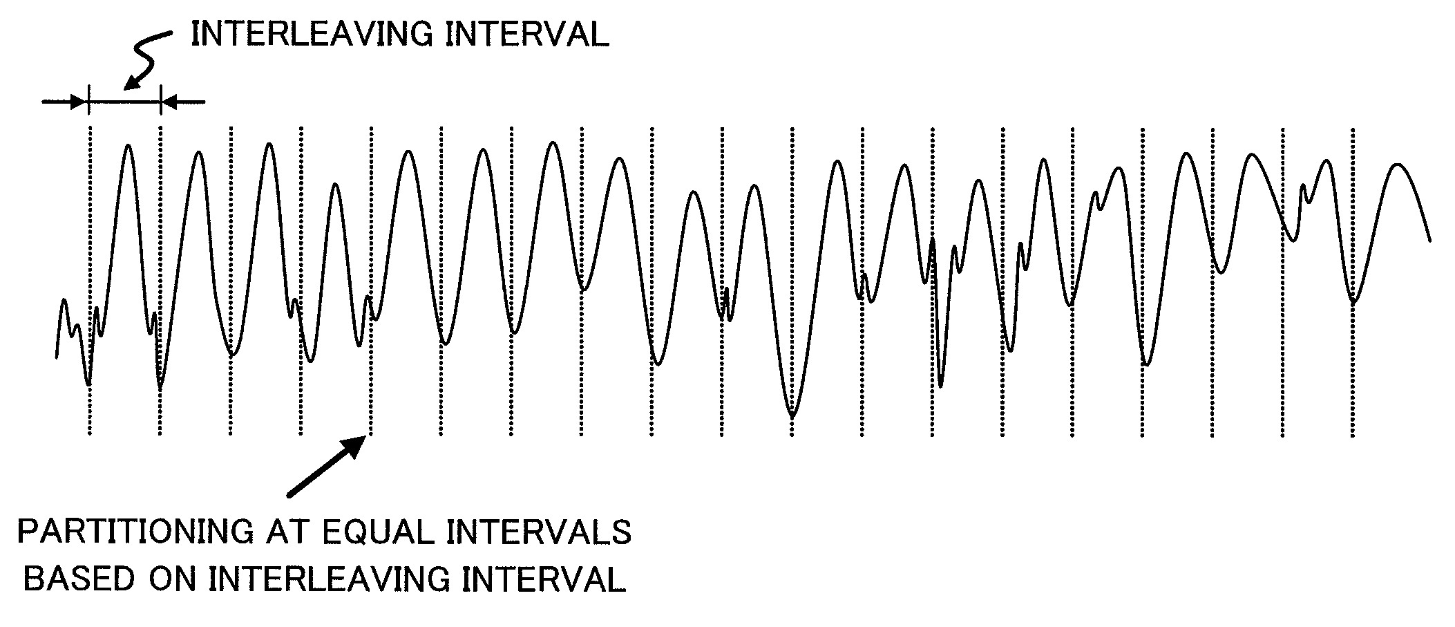
[0039]In spectrum difference computing section 102, the spectral coefficients obtained after the frequency transform are processed to compute the spectrum difference between the reference and the target signal in the frequency domain. The computation involves a series of processings such as interleaving the spectral coefficients, partitioning the coefficients into a plurality of bands, computing the difference of the bands between the reference channel and the...

embodiment 2

[0065]FIG. 9 shows an example where coding apparatus 100 according to of Embodiment 1 is applied to typical speech coding system (encoding side) 1000.

[0066]LPC analyzing section 401 is used to filter input speech signal s to obtain the LPC coefficient and the excitation signal. The LPC coefficients are quantized and encoded in LPC quantizing section 402 and the excitation signal are encoded in excitation coding section 403 to obtain the excitation parameters. The above components form main coder 400 of a typical speech coder.

[0067]Coding apparatus 100 is added to this main coder 400 to improve coding quality. Target signal et is obtained from the coded excitation signal from excitation coding section 403. Reference signal er is obtained in LPC inverse filter 404 by inverse filtering input speech signal s using the LPC coefficients. Pitch period T and interleave flag I_flag is computed by pitch period extracting and voiced / unvoiced sound deciding section 405 using input speech signal...


PUM


Abstract

A spectrum modifying method and the like wherein the efficiencies of the signal estimation and prediction can be improved and the spectrum can be more efficiently encoded. According to this method, the pitch period is calculated from an original signal, which serves as a reference signal, and then a basic pitch frequency (f0) is calculated. Thereafter, the spectrum of a target signal, which is a target of spectrum modification, is divided into a plurality of partitions. It is specified here that the width of each partition be the basic pitch frequency. Then, the spectra of bands are interleaved such that a plurality of peaks having similar amplitudes are unified into a group. The basic pitch frequency is used as an interleave pitch.

Description

TECHNICAL FIELD[0001]The present invention relates to a speech coding apparatus and a spectrum modification method.BACKGROUND ART[0002]The speech codec that encodes a monaural speech signal is the norm now. Such a monaural codec is commonly used in the communication equipment such as a mobile phone and teleconferencing equipment where the signal usually comes from a single source, for example, human speech.[0003]In the past, due to the limitation of the transmission bandwidth and the processing speed of DSPs, such a monaural signal is used. However, the technology progresses and bandwidth improves, and this constraint is slowly becoming less important. Quality of speech on the other hand becomes a more important factor to be considered. One drawback of the monaural speech is that the monaural speech does not provide spatial information such as sound imaging or position of the speakers and the like. Therefore, a factor to be considered is to achieve good stereo speech quality at the ...

Claims


Application Information

Patent Timeline
IPC IPC(8): G10L11/04G10L19/032G10L25/90
CPCG10L19/008G10L19/09G10L19/0204
Inventor TEO, CHUN WOEINEO, SUA HONGYOSHIDA, KOJIGOTO, MICHIYO
Owner III HLDG 12 LLC
Why Eureka
Try Eureka