Communication system and method for assigning addresses

Inactive Publication Date: 2008-07-24
DENSO CORP
View PDF4 Cites 44 Cited by
  • Summary
  • Abstract
  • Description
  • Claims
  • Application Information

AI Technical Summary

Benefits of technology

[0010]In view of the above-described problems, it is an object to provide a communication system and a method of address assignment in which a correct address can be assigned to each slave unit regardless of its connection position on the network line, and the wiring for the connection to the network line from each slave unit is simplified. In accordance with an aspect of the present invention, a communication system includes a plurality of slave units respectively associated with a unique quantity, a master unit

Problems solved by technology

In such a conventional system, two problems exist.
Consequently, two connectors are necessary for the bus line to enter and exit each slave unit, and wiring is complicated.
When a mistake occurs in the connection position of a s

Method used


Image

  • Communication system and method for assigning addresses
  • Communication system and method for assigning addresses
  • Communication system and method for assigning addresses

Examples


first embodiment

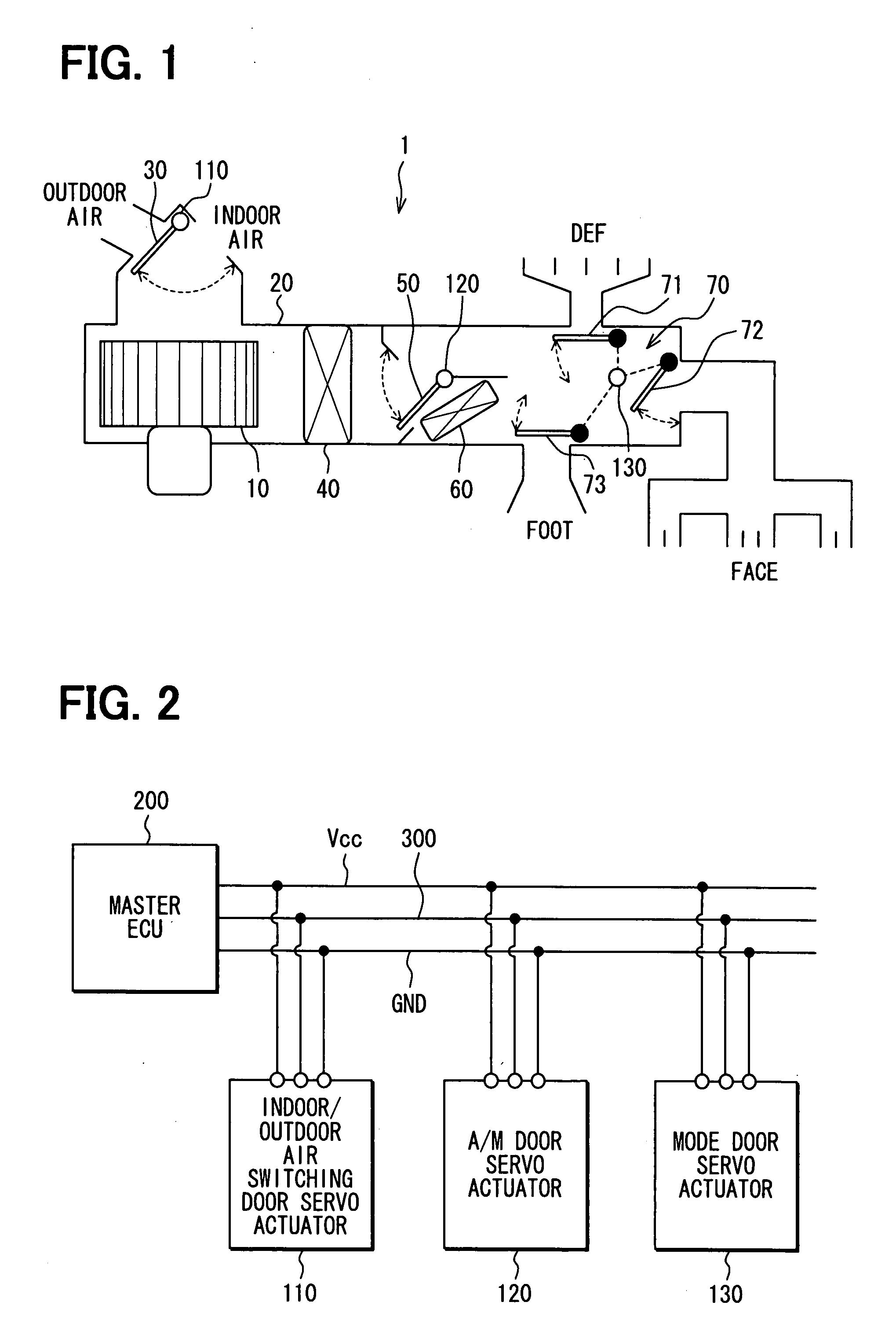
[0049]A first preferred embodiment of the present invention applied to an air conditioning system for vehicle will be described with reference to FIGS. 1-8. FIG. 1 shows the overall configuration of the air conditioning system 1. The air conditioning system 1 selects air entering an air conditioning case 20 from a blower fan 10 with an indoor / outdoor air switching door 30. The air conditioning system 1 cools the introduced air by a cooling heat exchanger 40. The open degree control of an air mixing door 50 adjusts a distribution ratio between the air leading to a heating heat exchanger 60 and the air bypassing the heat exchanger 60 in the air that has passed the cooling heat exchanger 40. After this, the air conditioning system 1 makes conditioned air by mixing air that passes through and air that bypasses the heating heat exchanger 60. Finally the air conditioning system 1 controls the open degree pattern of mode doors 70 (71,72,73), which open or close each outlet, and adjusts the...

second embodiment

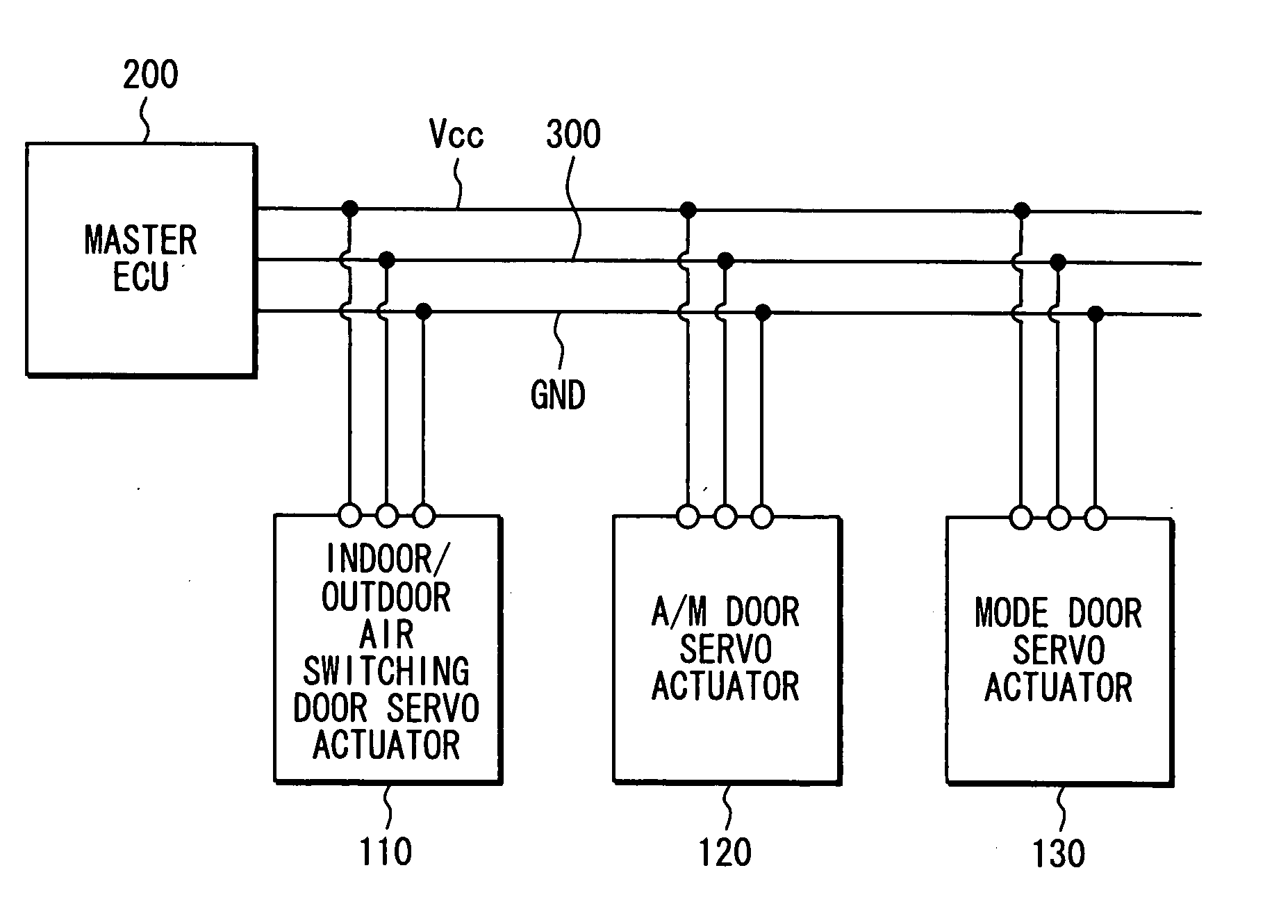
[0088]The second embodiment concerning the present invention is explained referring to FIG. 9. In this embodiment, the LIN bus line 300 forms a loop, and each door servo actuator 110,120,130 is connected to the single LIN bus line 300 in a common manner. When the LIN bus line 300 is configured as shown, even if one point on the LIN bus line 300 is cut by some kind of malfunction, each door servo actuator 110,120,130 can still communicate with the master ECU 200, and the reliability of the system 1 improves.

third embodiment

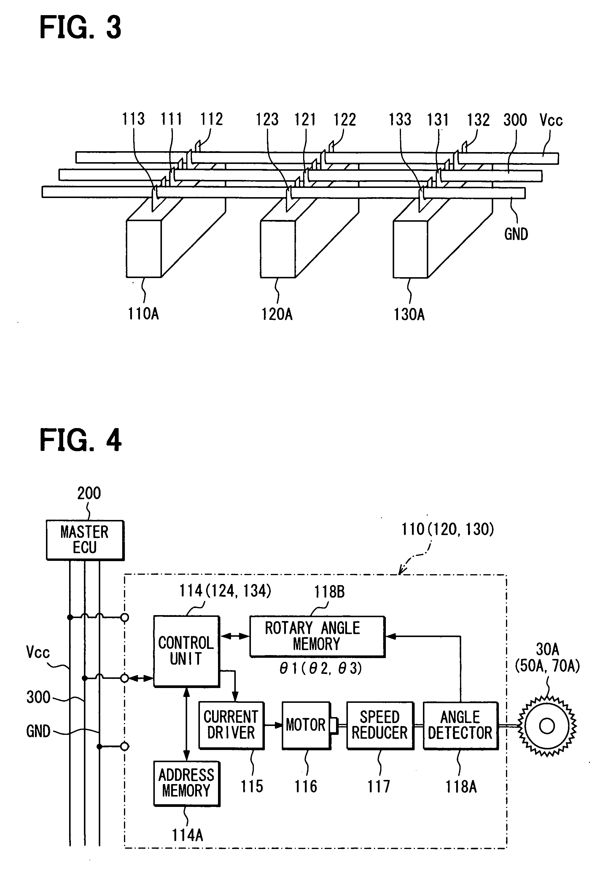
[0089]In first embodiment, the address is assigned for each door servo actuator 110,120,130 by using a counter value corresponding to the maximum operation degree as the unique quantity. But, for example, each actuator 110,120,130 may use a current value of the driving current when the current driver 115 supplies current to the motor 116 as the unique quantity.

[0090]The motor 116 usually has to be supplied with a driving current to generate torque depending on the load torque. The torque necessary to rotationally drive the doors 30,50,70 differs from one door to the other because the doors 30,50,70 are different regarding size and the forces from passing air.

[0091]In the third embodiment, each door servo actuator 110,120,130 stores a current value of the driving current supplied from current driver 115. The master ECU 200, as shown in FIG. 12, stores the current values corresponding to the classification of each door servo actuator 110,120,130 and the corresponding addresses.

[0092]R...


PUM


Abstract

A master ECU instructs door actuators having a counter value of θ n (where n=1,2,3) to set the address n as their unique network addresses. A control unit in each door servo actuator determines whether a counter value (θ n) that is the subject of a query from the master ECU corresponds to its own counter value, and the control unit sets the address n, when the control unit determines that the counter value (θ n) of the query corresponds to its own counter value. The counter value (θ n) is a unique quantity associated with each servo actuator

Description

CROSS REFERENCE TO RELATED APPLICATION[0001]This application is based on Japanese Patent Application No. 2006-243033 filed on Sep. 7, 2006, the disclosure of which is incorporated herein by reference.FIELD OF THE INVENTION[0002]The present invention relates to communication system and method for assigning addresses of a plurality of slave units in communication system communicating between a master unit and a plurality of slave units.BACKGROUND OF THE INVENTION[0003]For example, a known communication system is described in JP-A-H09-116565, which shows a connection known as a daisy chain. This connection has a bus line extending from a master unit to an upstream slave unit. The bus line further extends sequentially from the upstream slave unit to downstream slave units.[0004]Also, in the apparatus of JP-A-H09-116565, the bus line from the master unit is connected to the upstream slave unit (the slave unit closest to the master unit). Each slave unit is able to communicate with the ma...

Claims


Application Information

Patent Timeline
IPC IPC(8): G06F13/18
CPCH04L12/403B60H1/00842H04L2012/40273
Inventor MIYAZAWA, KAZUHIRO
Owner DENSO CORP
Why Eureka
Try Eureka