Ozone producing system

a production system and ozone technology, applied in the field of ozone production system, can solve the problems of inadequate temperature lowering inside the electrolytic cell, lowering the efficiency of ozone gas concentration or electric current, etc., and achieve the effects of suppressing the rise of temperature in the electrolytic cell, uniform temperature, and enhancing cooling

Inactive Publication Date: 2008-07-31
CHLORINE ENGINEERS CORP LTD
View PDF14 Cites 4 Cited by
  • Summary
  • Abstract
  • Description
  • Claims
  • Application Information

AI Technical Summary

Benefits of technology

[0007]Therefore, the object of the present invention is to solve the problems of said conventional methods, by enhancing cooling effect, suppressing temperature rise in the electrolytic cell caused by heat generation during electrolysis, and further, maintaining uniform temperature in the electrolytic cells at the time when ozone gas is produced by water electrolysis, so as to obtain ozone gas at a high efficiency and to prolong various members composing the electrolytic cells.
[0008]In order to solve said problems, the present invention constitutes an ozone producing system, comprising a perfluorocarbon polymer ion exchange membrane 9, an anode 8 supported with ozone generation catalyst on an electrically conductive porous material and a cathode 10 supported with platinum catalyst tightly installed on each side of said ion exchange membrane 9, an anode compartment frame 6 installed on the back face of said anode 8, an anode compartment 1 formed between the internal surface of said anode compartment frame 6 and the back of said anode 8, a cathode compartment frame 12 installed on the back of said cathode 10 via a current collector 11, a cathode compartment 2 formed between the internal surface of said cathode compartment frame 12 and the back of said current collector 11, and cooling jackets 16, 16 installed so as to tightly attach to the external surface of said anode compartment frame 6 and said cathode compartment frame 12, characterized in that in an ozone producing electrolytic cell 3 for producing ozone gas from pure water supplied to said anode compartment 1; multiple numbers of grooves 13 are formed on the internal surfaces of said anode compartment frame 6 and said cathode compartment frame 12; an anolyte gas-liquid separation tower 4 to separate anolyte from ozone-containing gas generated from said anode compartment 1, being connected to said anode compartment 1 and a catholyte gas-liquid separation tower 5 to separate catholyte from hydrogen gas generated from said cathode compartment 2, being connected to said cathode compartment 2 are installed outside of said electrolytic cell 3 for ozone producing; achieving enhanced cooling effect of anolyte and catholyte and producing ozone gas at a high efficiency.

Problems solved by technology

However, the system disclosed by JP 11-315389 A demonstrated insufficient temperature lowering; it enabled to suppress temperature rise inside the anode compartment and lower the electrolytic cell temperature, but still allowed a high temperature to remain due to the lack of cathode cooling and thus showed inadequate temperature lowering inside the electrolytic cell, especially at the interfaces between the ion exchange membrane and the anode, and the ion exchange membrane and the cathode, where electrolytic reaction is being performed.
Because of these reasons, uneven temperature distribution occurs inside the electrolytic cell, causing deterioration of structural members, leading to lowered ozone gas concentrations or electric current efficiency with time lapse and eventually resulting in necessity for frequent replacement of structural members to maintain satisfactory performance.

Method used


Image

  • Ozone producing system
  • Ozone producing system
  • Ozone producing system

Examples


example

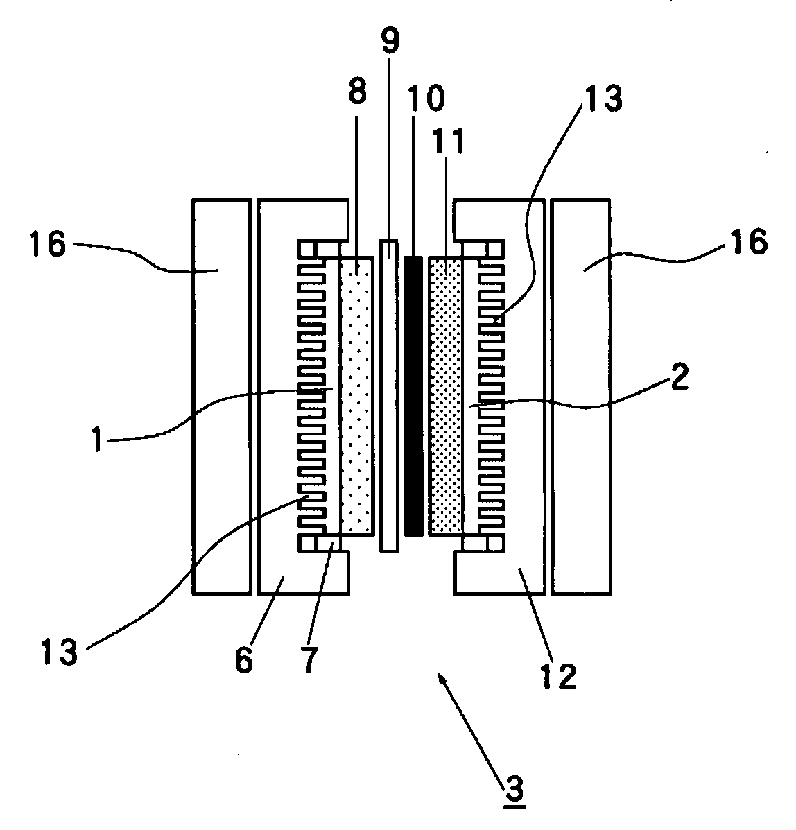
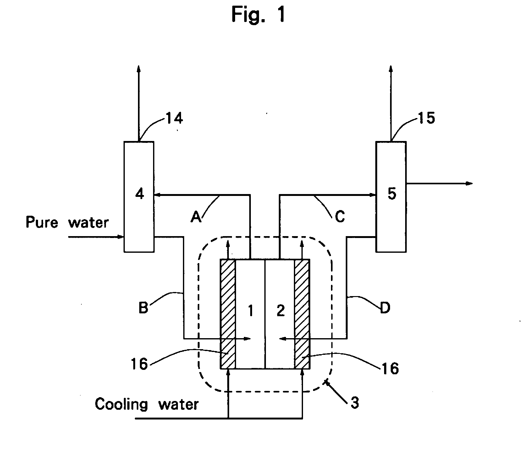
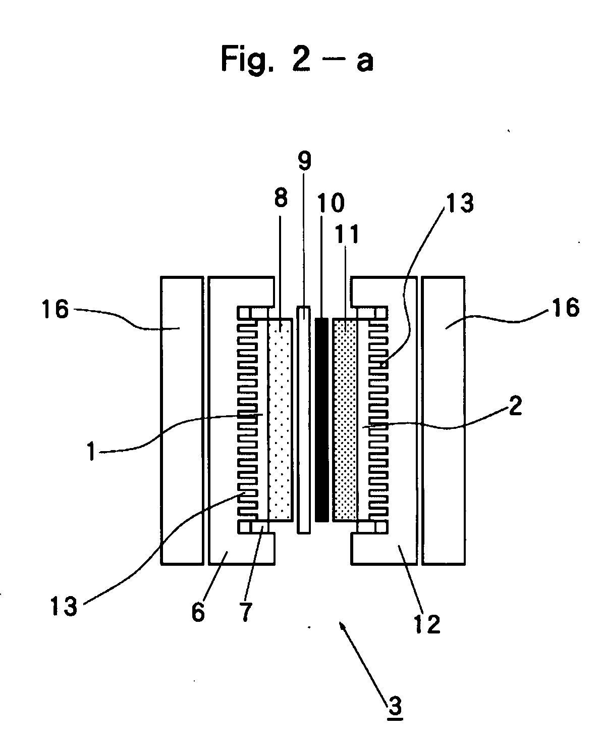
[0025]As an example of the present invention, electrolysis was conducted at a current density 200 A / dm2 using the ozone producing system shown in FIG. 1. In this experiment, the water electrolysis cell for ozone production, shown as 3 in FIG. 1 employed the cell shown in FIG. 2-a and FIG. 2-b. In FIG. 2-a and FIG. 2-b, 8 is the anode supported with ozone generation catalyst on the electrically conductive porous material, 9 is a perfluorocarbon sulfuric acid polymer ion exchange membrane, 10 is a cathode supported with platinum catalyst. Whereas, 6 is an anode compartment frame, and 12 is a cathode compartment frame, on which multiple numbers of grooves 13 as explained in FIG. 3 are formed. Anolyte and catholyte were circulated between the anode compartment 1 and the anolyte gas-liquid separation tower 4, and the cathode compartment 2 and the catholyte gas-liquid separation tower 5, respectively. The externals of the anode compartment frame 6 and the cathode compartment frame 12 are ...


PUM

PropertyMeasurementUnit
electrolytic temperatureaaaaaaaaaa
temperatureaaaaaaaaaa
current densityaaaaaaaaaa

Abstract

According to the system by the present invention, multiple numbers of grooves 13 are formed on the internal surface of said anode compartment frame 6 and said cathode compartment frame 12, an anolyte gas-liquid separation tower 4 to separate anolyte from ozone-containing gas generated from said anode compartment 1, being connected to said anode compartment 1 and a catholyte gas-liquid separation tower 5 to separate catholyte from hydrogen gas generated from said cathode compartment 2, being connected to said cathode compartment 2 are installed outside of said electrolytic cell 3 for ozone producing; achieving enhanced cooling effect of anolyte and catholyte and producing ozone gas at a high efficiency.

Description

BACKGROUND OF THE INVENTION[0001]1. Field of the Invention[0002]This invention relates to an ozone producing system which can achieve prolonged lives of various members composing an electrolytic cell, and can produce ozone gas at a higher efficiency, as well, by lowering temperatures inside the electrolytic cell when producing ozone gas by water electrolysis.[0003]2. Description of the Related Art[0004]The methods to produce ozone gas by means of water electrolysis are publicly known, where the applied electrolytic temperature is commonly around 30 degrees Celsius in order to manufacturing high concentration ozone gas at a high electric current efficiency.[0005]However, electrolytic cells used for ozone gas generation are heated by electrolysis to a temperature substantially in excess of 30 degrees Celsius and therefore, the internal temperature must be lowered by cooling the electrolytic cells. As a cooling method of electrolytic cells, such methods are known that as shown in FIG. ...

Claims


Application Information

Patent Timeline
Patent Type & Authority Applications(United States)
IPC IPC(8): C25B9/00
CPCC25B9/10C25B1/13C25B9/23C01B13/10
Inventor HASHIMOTO, TERUMIKATO, MASAAKIMANABE, AKIYOSHI
Owner CHLORINE ENGINEERS CORP LTD
Why Eureka
Try Eureka