Current source with indirect load current signal extraction

a current source and load current technology, applied in the direction of variable inductance, inductance, electric variable regulation, etc., can solve the problems of significant power loss, increase supply thermal stress, reduce power conversion efficiency, etc., and not directly

Active Publication Date: 2008-07-31
ANALOG DEVICES INT UNLTD
View PDF8 Cites 117 Cited by
  • Summary
  • Abstract
  • Description
  • Claims
  • Application Information

AI Technical Summary

Problems solved by technology

However, the load resistor RLoad used for sensing the load current causes significant power loss.
Moreover, for high current applications, this current control method not only reduces power conversion efficiency but also increases the supply thermal stress.
However, the control circuit 12 does not directly control the load current iLoad.
Therefore, the dynamic tracking performance of the converter 20 is compromised.
For applications that require a fast load current transient response, such as LED true color dimming control, sensing of the inductor current results in poor load dynamic performance.
However, the waveform of the load current iLoad controlled using the inductor current sensing method in FIG. 2 is not acceptable because the inductor current iL, instead of the load current iLoad, is used to track the reference signal Vref.
Therefore, the current control scheme illustrated in FIG. 2 is much slower than the current control scheme in FIG. 1, and cannot be used for applications requiring a fast dynamic response.

Method used


Image

  • Current source with indirect load current signal extraction
  • Current source with indirect load current signal extraction
  • Current source with indirect load current signal extraction

Examples


Embodiment Construction

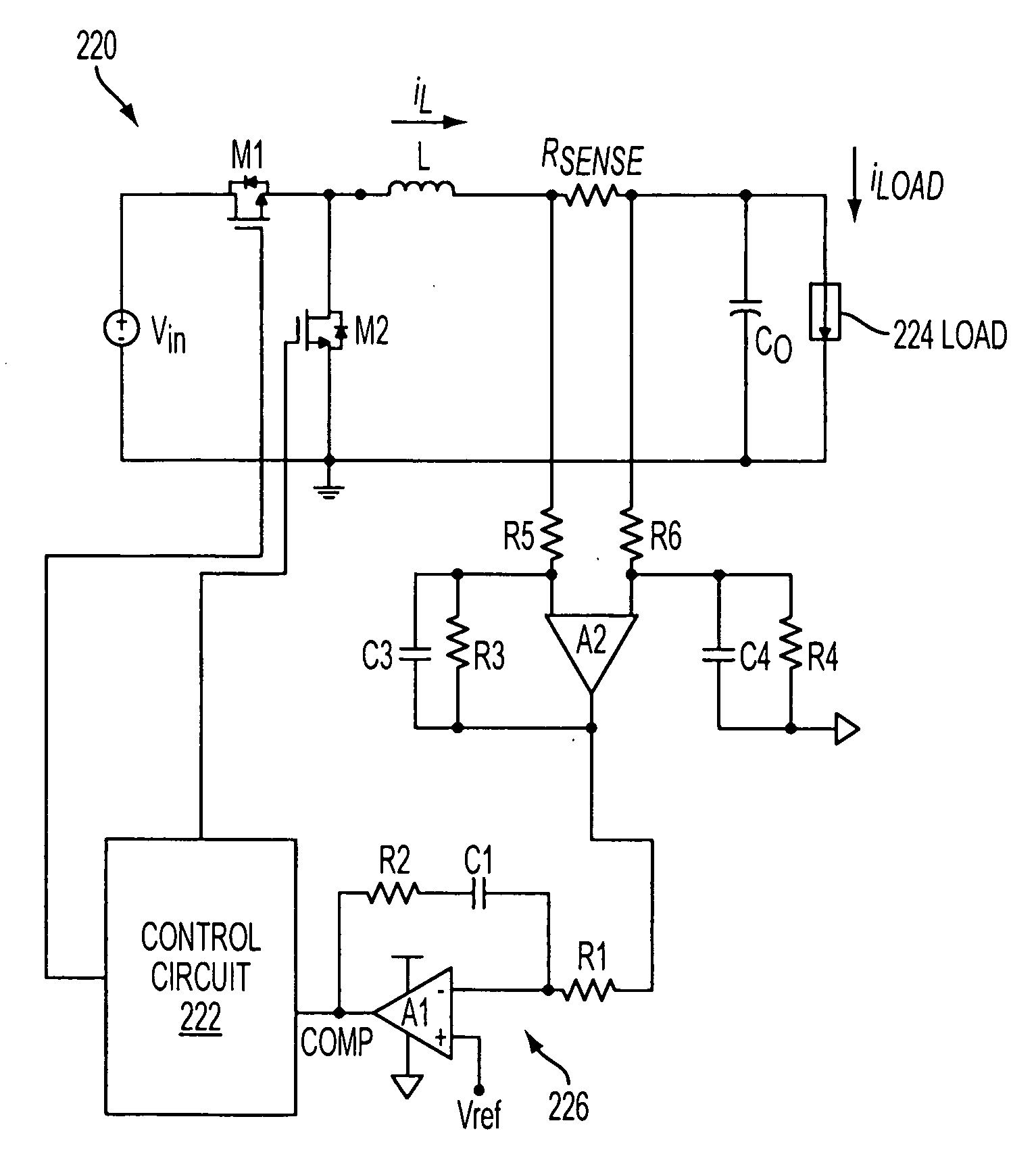
[0034]The present disclosure will be made using the example of a system for controlling output current of a step-down switching regulator for a LED driver. It will become apparent, however, that the concept of the disclosure is applicable to any circuitry that senses current in an inductive element of a switching circuit to control the output current of the switching circuit. For example, the indirect current sensing of the present disclosure also may be used to control other switching mode converters, such as boost, buck-boost, flyback, and forward converters.

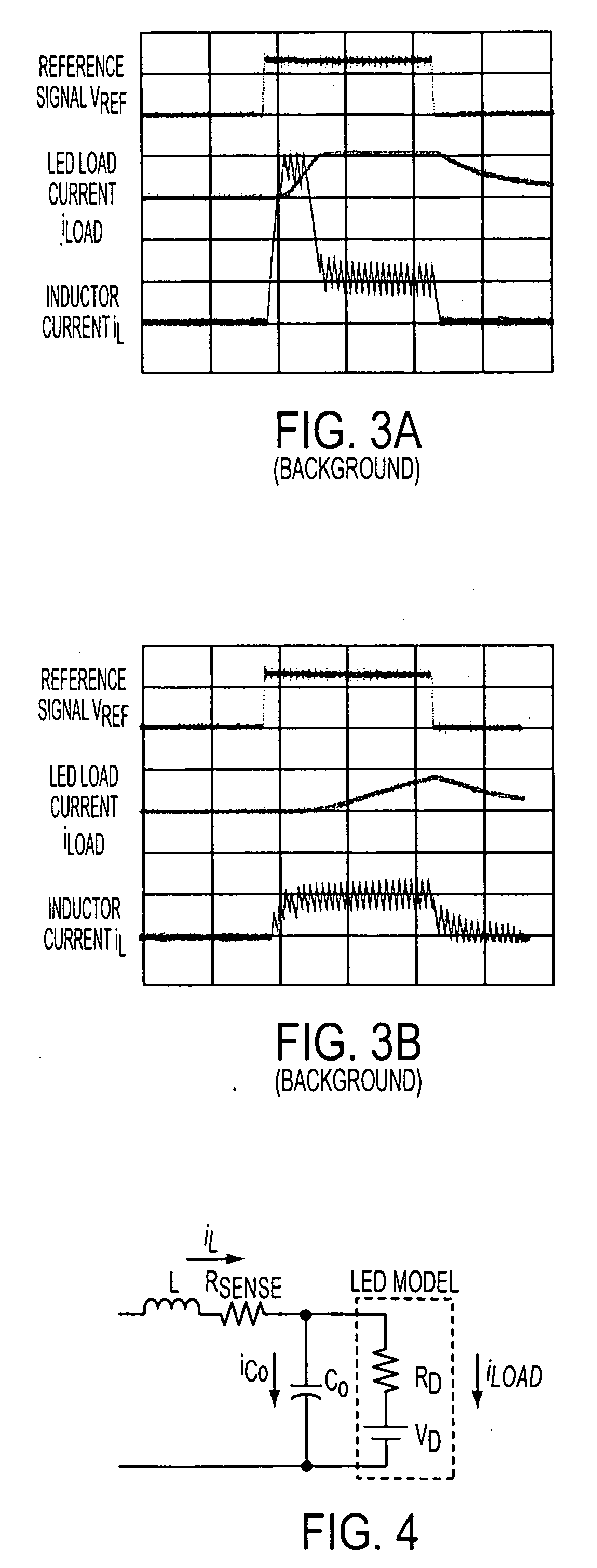
[0035]In accordance with an exemplary embodiment of the present disclosure illustrated in FIG. 4, a load supplied by a current source may include a LED. A model of a LED may be represented by voltage source VD connected in series with resistor RD corresponding to the dynamic resistance of the LED. The current source illustrated in FIG. 4 may include inductor L, sense resistor Rsense and output capacitor Co connected in a step-...


PUM


Abstract

A switching circuit for supplying current to a load has a switching element, an inductive element coupled to the switching element, and a load current extraction circuit responsive to current in the inductive element for producing a load current signal as a simulated current approximating current in the load.

Description

TECHNICAL FIELD[0001]The subject matter of this disclosure relates to power supply circuits, and more particularly to circuitry and methodology for indirect load current sensing in a switching circuit.BACKGROUND [0002]Some power supply circuits, such as light emitting diode (LED) drivers and laser diode drivers, require a current source with high output current. To achieve high efficiency, minimize device size and thermal stress, switching mode DC / DC converters may be utilized to provide a current source, especially in high current applications.[0003]FIG. 1 illustrates a conventional DC / DC converter 10 that may be used as a power supply for providing current to a load, such as a LED or laser diode. The converter 10 may be a synchronous step-down switching regulator including a pair of MOSFETs M1 and M2 controllable by a control circuit 12 to produce a required value of current iLoad in a load 14, such as a LED. The control circuit 12 may include a pulse width modulation (PWM) circui...

Claims


Application Information

Patent Timeline
Patent Type & Authority Applications(United States)
IPC IPC(8): G05F1/575H05B44/00
CPCH02M3/156Y02B20/347H05B33/0848H05B33/0818H05B45/14H05B45/38H05B45/375Y02B20/30
Inventor XIE, MANJINGZHANG, JINDONG
Owner ANALOG DEVICES INT UNLTD
Why Eureka
Try Eureka