Blade assembly in a combustion turbo-machine providing reduced concentration of mechanical stress and a seal between adjacent assemblies

a technology of combustion turbine and blade assembly, which is applied in the field of turbines, can solve the problems of small gap maintained between adjacent platforms, lack of sealing effectiveness, and high cost of devices to manufactur

Inactive Publication Date: 2008-07-31
SIEMENS ENERGY INC
View PDF46 Cites 52 Cited by
  • Summary
  • Abstract
  • Description
  • Claims
  • Application Information

AI Technical Summary

Problems solved by technology

While it would be desirable to have adjacent platforms abut in a perfect sealing relationship, the necessity to accommodate thermal growth and machining tolerances results in a small gap being maintained between adjacent platforms.
Generally, such devices are ge

Method used


Image

  • Blade assembly in a combustion turbo-machine providing reduced concentration of mechanical stress and a seal between adjacent assemblies
  • Blade assembly in a combustion turbo-machine providing reduced concentration of mechanical stress and a seal between adjacent assemblies
  • Blade assembly in a combustion turbo-machine providing reduced concentration of mechanical stress and a seal between adjacent assemblies

Examples


Embodiment Construction

[0017]Modern combustion turbine engines may utilize a portion of the compressed air generated by the compressor section of the engine as a cooling fluid for cooling hot components of the combustor and turbine sections of the engine. In an open loop cooling system design, the cooling fluid is released into the working fluid flow after it has removed heat from the hot component. For the most advanced engines that are designed to operate at the highest efficiencies, a closed loop cooling scheme may be used. In a closed loop cooling system the cooling fluid is not released into the working fluid in the turbine, but rather is cooled and returned to the compressor section. In these high efficiency engines, the effectiveness of the seal between adjacent rotating blade platforms is important.

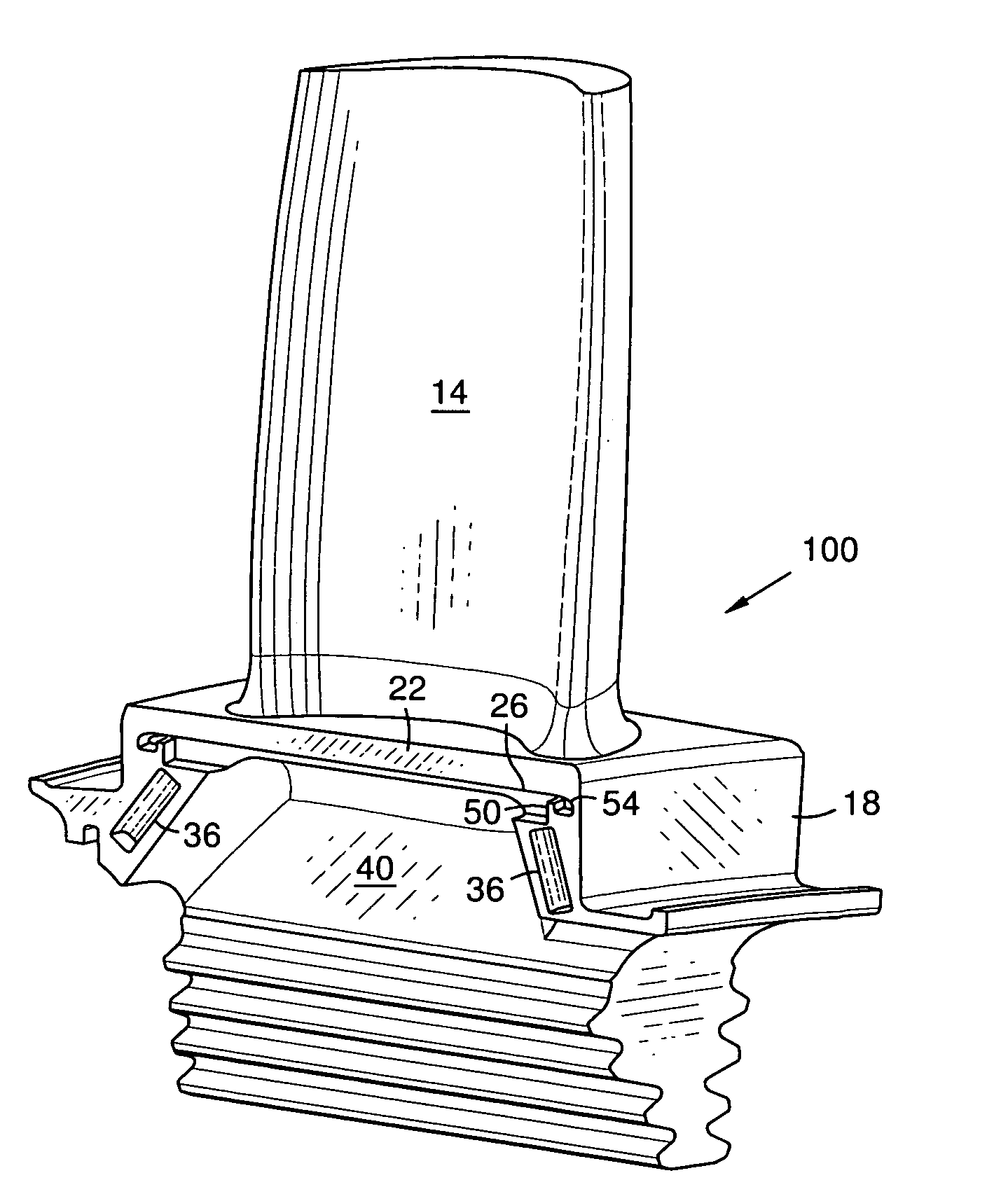
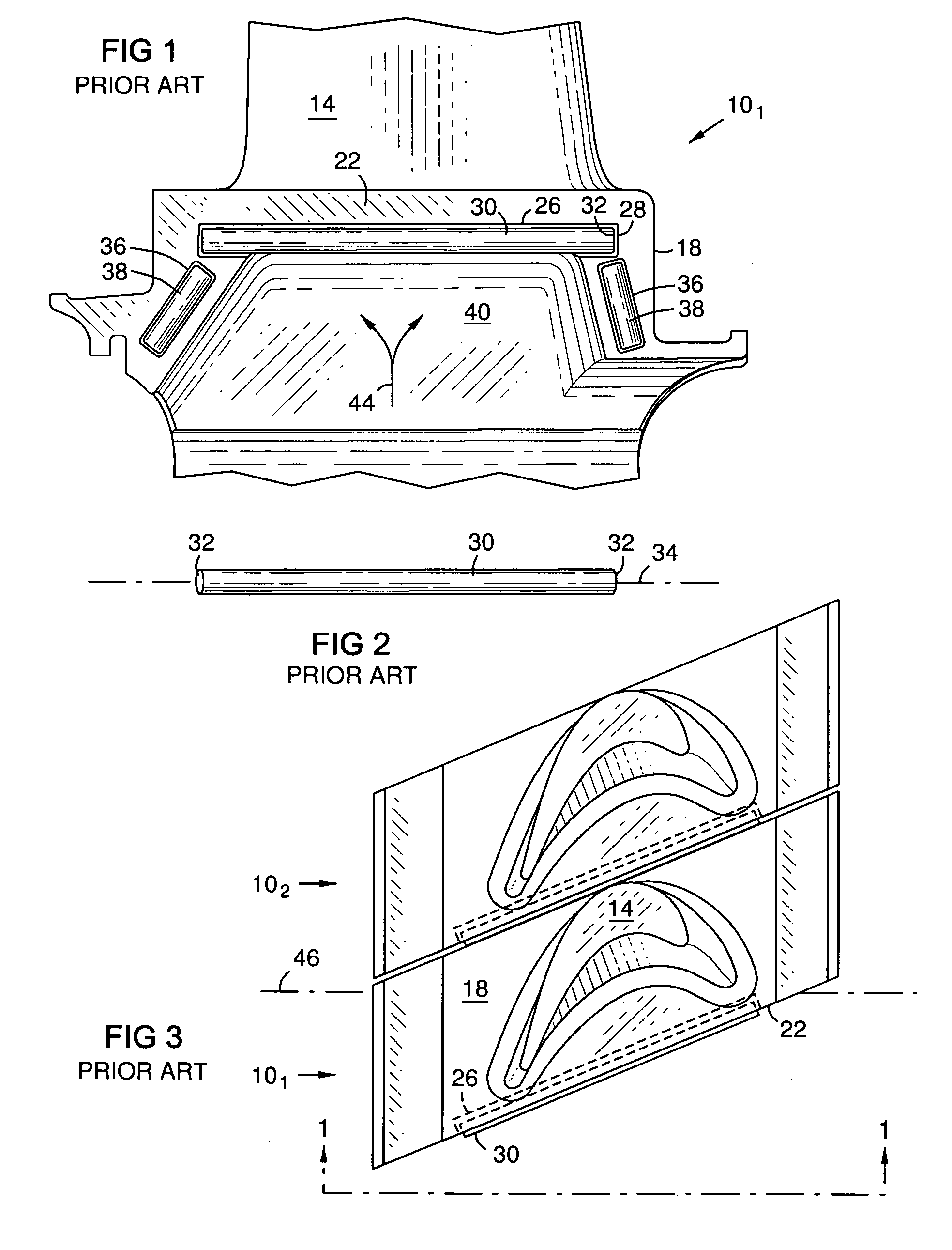
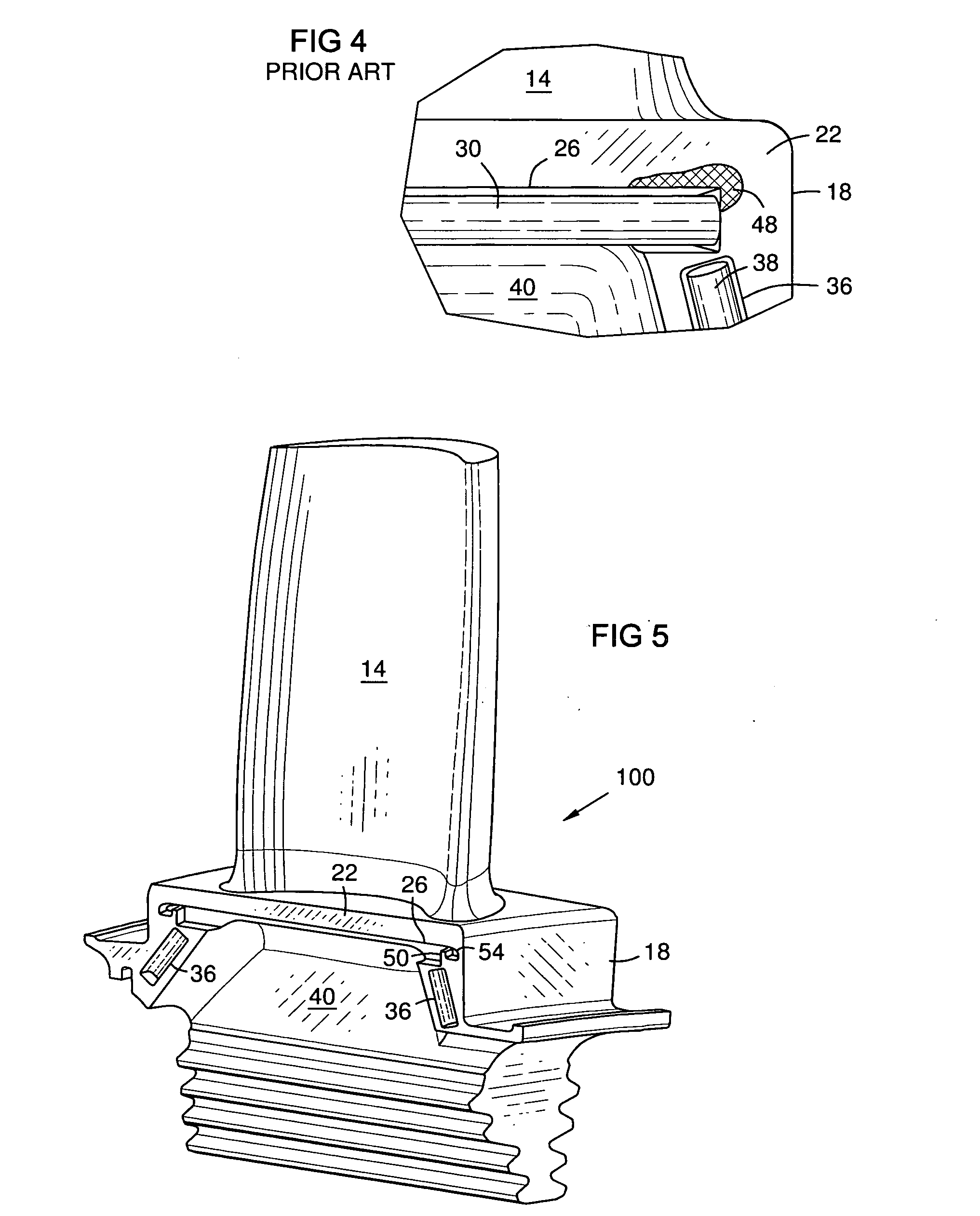
[0018]FIG. 1 illustrates a prior art rotatable blade assembly 101 as may be used in a combustion turbine engine. Assembly 101 includes a root section 40 for attaching the blade to a rotor assembly (not ...


PUM


Abstract

A blade assembly 100 (FIG. 5) configuration that includes a means for distributing mechanical stress (e.g., a stress dissipater 54) is provided. The stress dissipater is configured to reduce the concentration of a peak mechanical stress without compromising the effectiveness of a seal between adjacent rotating blade assemblies.

Description

FIELD OF THE INVENTION[0001]This invention relates generally to the field of turbo-machines, and more particularly to the field of gas or combustion turbines, and specifically to an apparatus for sealing a gap between adjacent platforms in a row of rotating blades in a combustion turbine engine.BACKGROUND OF THE INVENTION[0002]Turbo-machines such as compressors and turbines generally include a rotating assembly having a centrally located rotor shaft and a plurality of rows of rotating blades attached thereto, and a corresponding plurality of rows of stationary vanes connected to the casing of the turbo-machine and interposed between the rows of rotating blades. A working fluid such as air or combustion gas flows through the rows of rotating blades and stationary vanes to transfer energy between the working fluid and the turbo-machine.[0003]A blade of a turbo-machine typically includes a root section attached to the rotor, a platform section connected to the root section, and an airf...

Claims


Application Information

Patent Timeline
IPC IPC(8): F03B3/12
CPCF01D5/147F01D11/006Y10S416/50F05D2250/71F05D2250/14F05D2260/94F01D5/22
Inventor DECARDENAS, RAFAEL A.
Owner SIEMENS ENERGY INC
Why Eureka
Try Eureka