Device and method for loading and unloading a machining machine for machining boards

a technology for machining machines and machining boards, which is applied in the direction of metal-working holders, large fixed members, supporters, etc., can solve the problems of machining systems that should take up the least amount of space, changing tables are not readily accessible, and boards must be moved horizontally and vertically. it is easy to load and unload changing tables and reduce the time required for loading and unloading. , the effect of simplifying the loading and unloading

Active Publication Date: 2008-07-31
BYSTRONIC LASER
View PDF8 Cites 16 Cited by
  • Summary
  • Abstract
  • Description
  • Claims
  • Application Information

AI Technical Summary

Benefits of technology

[0018]An object of the present invention is to avoid the aforementioned disadvantages and to create a device and a method for loading and unloading a machining machine for machining boards which will simplify the loading and unloading of changing tables and will reduce the time required for loading and unloading.
[0024]This results in, among other things, the fact that the unloading place can be set up at a great distance spatially from the loading place, e.g., in such a way that a first changing table at the loading place and a second changing table at the unloading place are accessible simultaneously so that the two changing tables can be loaded and / or unloaded independently of one another, e.g., simultaneously. The latter merely presupposes that the loading device and the unloading device are designed for this purpose and can be controlled accordingly. In this way, it is possible to perform the loading and unloading of several changing tables in independent parallel processes. The parallel process management contributes toward an increase in the conveyance capacity of the conveyance device.
[0025]Due to the fact that the unloading place of the respective changing table is provided in an area above the second storage place, the prerequisite for a simplified design of the conveyance device and in particular the unloading device is also met. Under the aforementioned prerequisite, the distance between the unloading place and the second storage place is relatively short. To unload a changing table, the machined boards must subsequently be conveyed by the unloading device over only a short distance from the unloading place to the second storage place. It is also possible to design the unloading device so that a machined board need be moved only along a straight path (i.e., in a one-dimensional movement) in unloading. Such an unloading device can be implemented with especially simple (conventional) means and can be controlled relatively easily.
[0026]In one embodiment of the present invention, a board deposited on the respective changing table can be picked up by the unloading device at the unloading place, separated from the changing table and deposited at the second storage place after removal of the changing table. To this end, the unloading device may be equipped with a gripping device for gripping the boards that are to be conveyed and with a movement device for moving the gripping means. For example a hoisting device which allows a one-dimensional movement (e.g., in a vertical direction) may be provided as the movement device for the gripping device of the unloading device. Such a hoisting device can be implemented especially easily using conventional techniques and devices. Another advantage of this embodiment may be seen in the fact that the unloading device takes up very little space in unloading a changing table. The unloading device may essentially be arranged above the second storage place and usually does not take up any floor space—in a vertical projection onto the storage place and / or the floor—does not take up any more floor space than that required by the storage system.
[0029]In one variant, the guide is situated between the changing table changer and the parking place in such a way that it passes by and above one of the storage places. This variant is especially space saving.

Problems solved by technology

Secondly, the machining system should take up the least possible amount of space, e.g., with regard to the required floor space and / or height in a room.
The latter variant has the advantage over the variant mentioned previously that the changing table changer and the storage system jointly take up a particularly small amount of floor space, but it also has the disadvantage that the changing table is not readily accessible (because of the arrangement of the storage system).
For the case when the respective loading place and the respective unloading place for the boards are provided on the changing table changer, the two variants mentioned above have the disadvantage that boards must be moved both horizontally and vertically in both loading and unloading a changing table over relatively long paths which often involve curves.
For this reason, conveyance of the boards between the loading place and / or the unloading place and the respective storage places is associated with complicated movements of the boards, usually in three dimensions.
The designs of the loading device and / or unloading device are complicated accordingly.
In addition, this requires a complicated control of the movement processes.
Another disadvantage may be regarded as the fact that the loading and unloading of changing tables may be time-consuming if the loading place and the unloading place of the changing tables are each provided at the place of the changing table changer, i.e., essentially at the same location.
Simultaneous loading and unloading of various changing tables are usually impossible.
This has a negative effect on the conveyance capacity of the conveyance device.

Method used


Image

  • Device and method for loading and unloading a machining machine for machining boards
  • Device and method for loading and unloading a machining machine for machining boards
  • Device and method for loading and unloading a machining machine for machining boards

Examples


Embodiment Construction

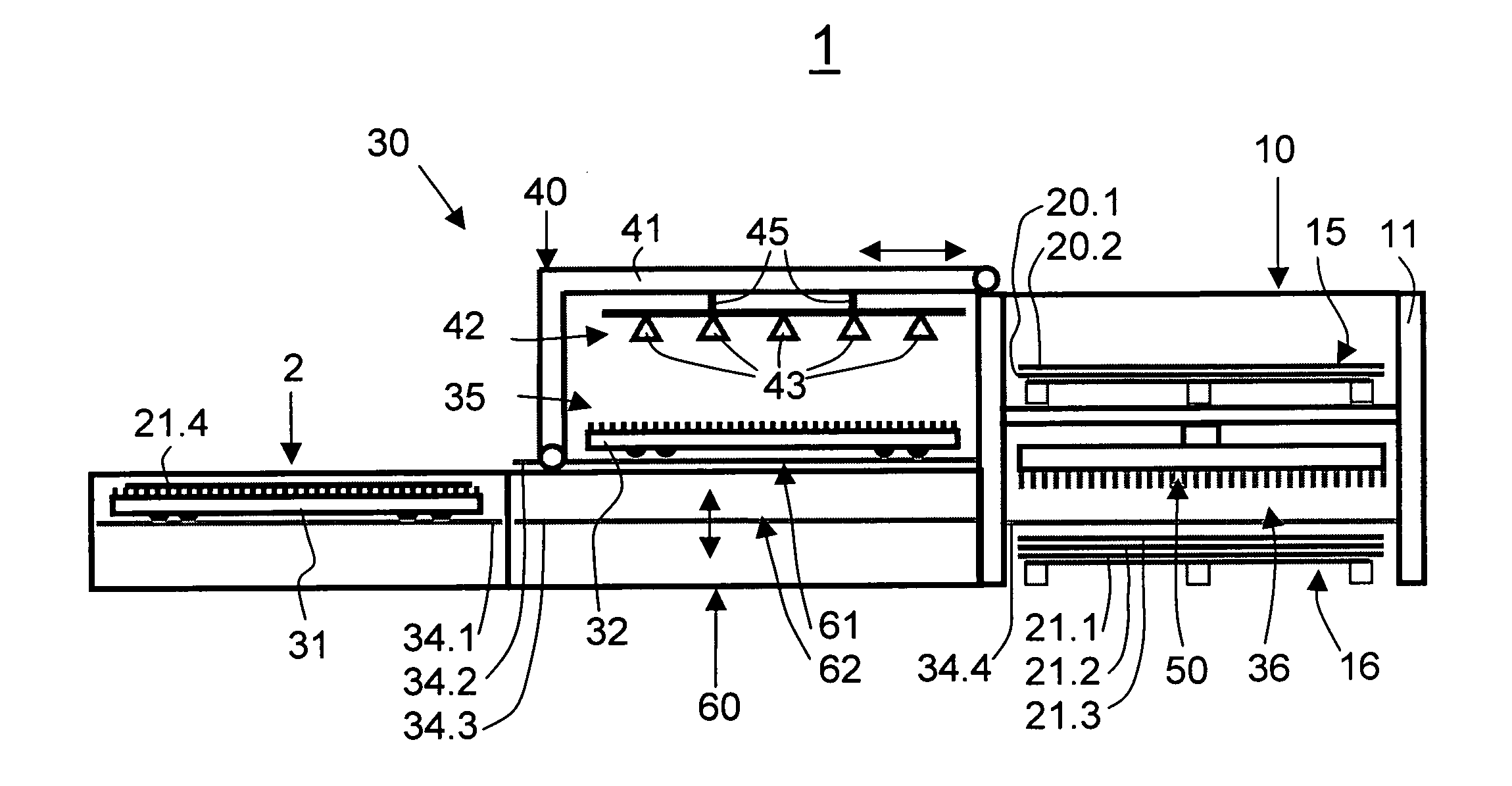
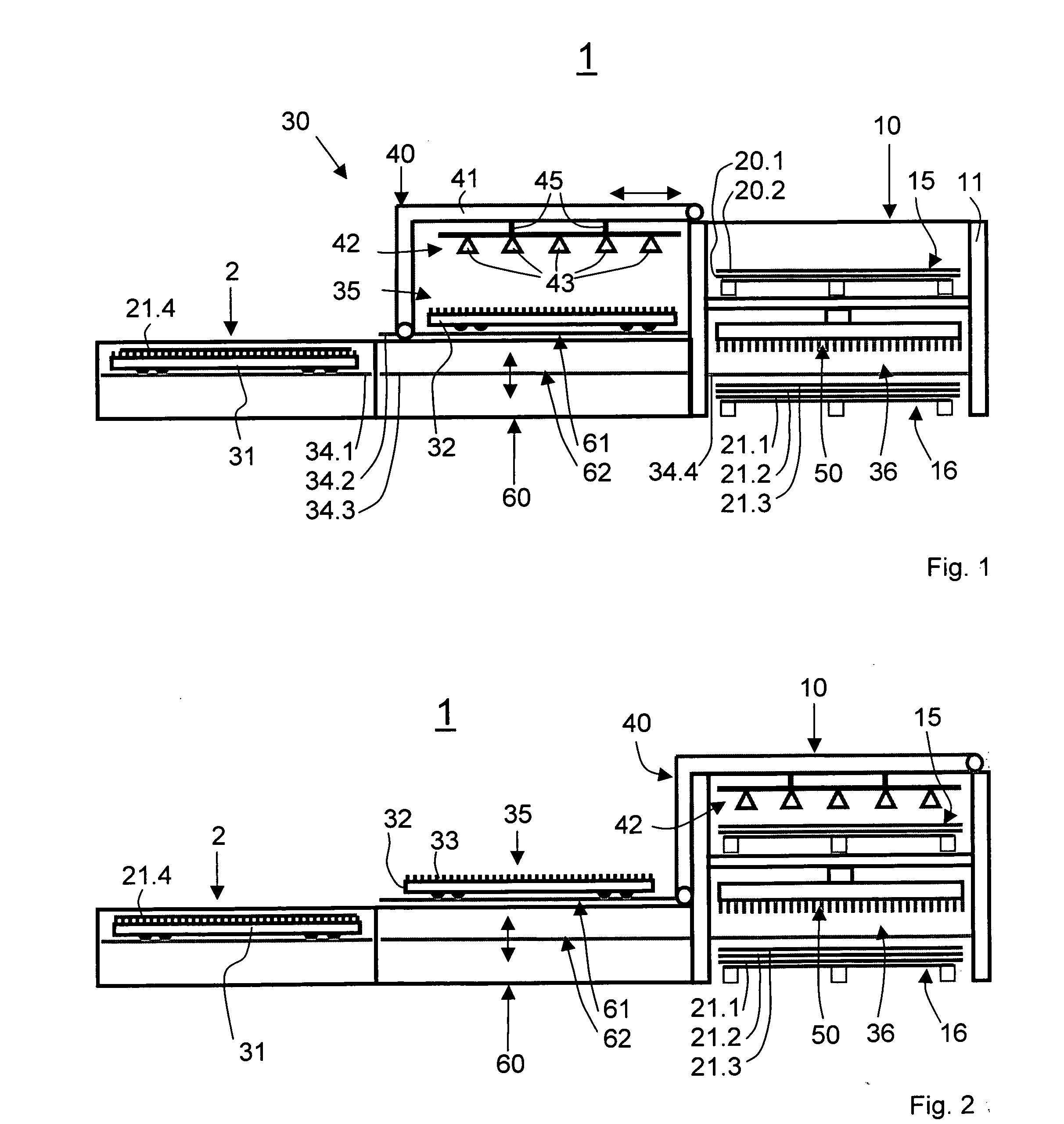
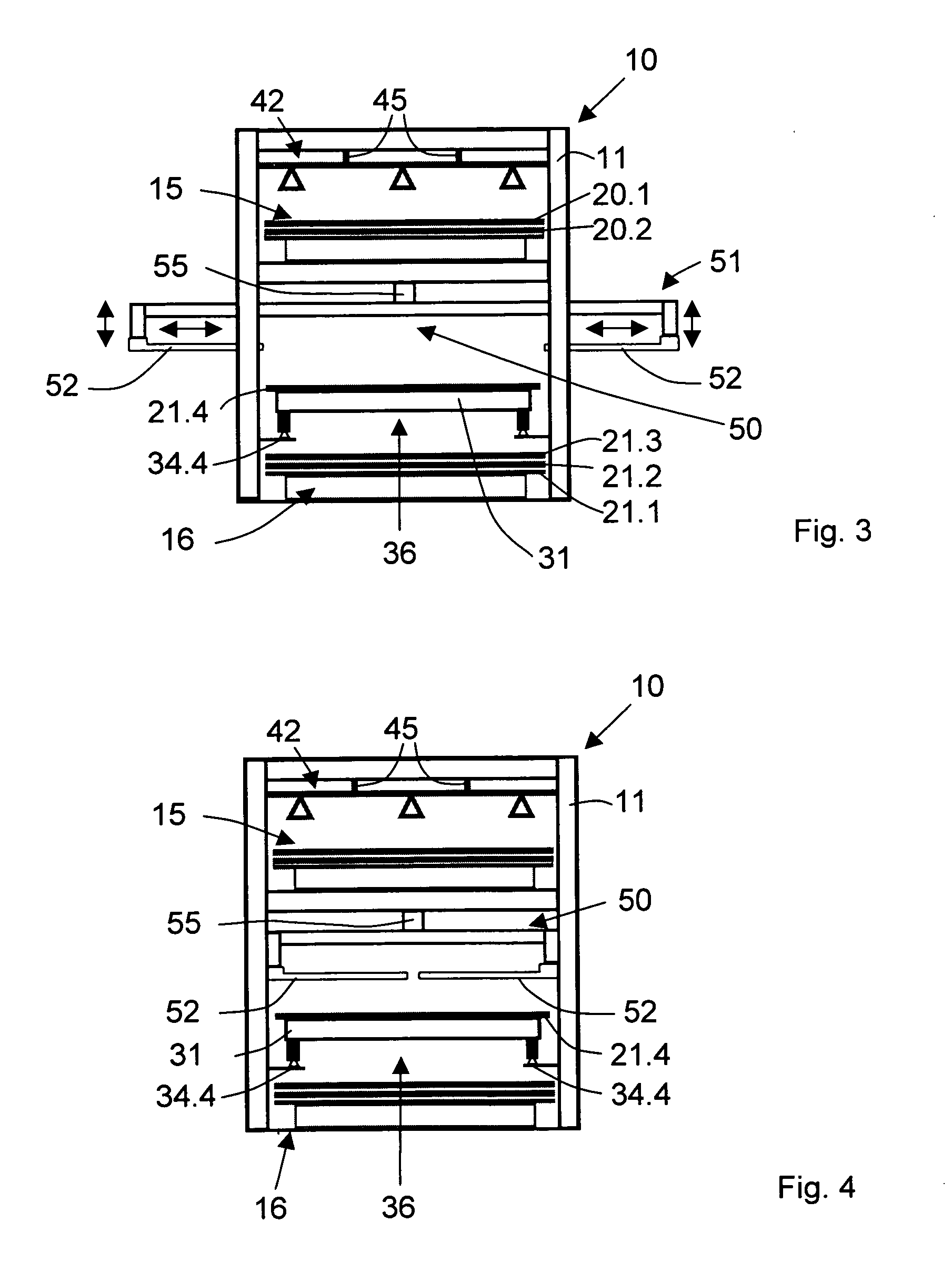
[0039]FIG. 1 shows an automatic machining system 1 for boards, including a machining machine 2 for machining boards, a storage system 10 for boards that are to be machined and boards that have already been machined and a conveyance device 30 for conveying the boards that are to be machined and for conveying the boards that have already been machined between the storage system 10 and the machining machine 2.

[0040]The machining machine 2 may be, for example, a machine for cutting boards, which is therefore equipped with a cutting tool (e.g., a mechanical cutting tool, a device for laser cutting, a device for water jet cutting, etc.). However, the type of machining of the boards is not relevant within the scope of the present invention. The present descriptions of the machining system 1 therefore do not include any details indicating the type of machining and / or any concrete machining operation.

[0041]In the present discussions of the machining system 1, different boards to be machined ...


PUM

PropertyMeasurementUnit
areaaaaaaaaaaa
distanceaaaaaaaaaa
heightaaaaaaaaaa

Abstract

A method for loading and unloading a machining machine for machining boards that includes for loading the machining machine, the changing table is loaded with a board to be machined, whereby the board is separated from the first storage place and is deposited on a changing table. The changing table is conveyed together with the board to the machining machine. For unloading the machining machine, the changing table is conveyed together with a machined board to the second storage place and is then unloaded, wherein the machined board is separated from the changing table and deposited on the second storage place, wherein the unloading of the changing table includes conveying the changing table and the machined board to an unloading place in an area above the second storage place and the machined board is separated from the changing table at the unloading place.

Description

RELATED APPLICATIONS[0001]Applicants claim, under 35 U.S.C. § 119, the benefit of priority of the filing date of Dec. 19, 2006 of a European patent application, copy attached, Serial Number 06405534.6 filed on the aforementioned date, the entire contents of which is incorporated herein by reference.BACKGROUND[0002]1. Technical Field[0003]The present invention relates to a device for loading and unloading a machining machine for machining boards.[0004]2. Background Information[0005]The term “board” as used here is understood in general to refer to a relatively thin flat object made of a solid material (e.g., metal, stone or wood).[0006]In industrial manufacturing, devices and methods for machining boards are used in a variety of ways, e.g. for cutting, coating or machining surfaces of boards. To achieve a high productivity, automatic machining systems are generally used, including not only a machining machine for boards but also an automatic device for loading and unloading the machi...

Claims


Application Information

Patent Timeline
Patent Type & Authority Applications(United States)
IPC IPC(8): B23Q15/00B65H29/00
CPCB21D43/18B21D43/20B23Q1/66Y10T29/5124B65G60/00Y10T483/16B23Q7/103
Inventor JOST, STEFANZIMMERLI, JURGMESSER, JURG
Owner BYSTRONIC LASER
Why Eureka
Try Eureka