
Check Matrix Generating Apparatus and Communication Apparatus

a matrix generation and communication apparatus technology, applied in the direction of coding, instruments, code conversion, etc., can solve the problems of increasing the hammering distance of the code word, the inability to correct the prior art error correction methods, and the inability to conduct much time, so as to achieve easy generation of the check matrix, good error correction capability, and stable characteristics

Inactive Publication Date: 2008-07-31
MITSUBISHI ELECTRIC CORP
View PDF3 Cites 23 Cited by
  • Summary
  • Abstract
  • Description
  • Claims
  • Application Information

AI Technical Summary

Benefits of technology

[0025]The present invention therefore offers an advantage of being able to easily generate a check matrix for Irregular-LDPC codes which is deterministic, which have stable characteristics, which has a good error correction capability, and which supports various ensembles, various code lengths, and various coding rates in a short time.

Problems solved by technology

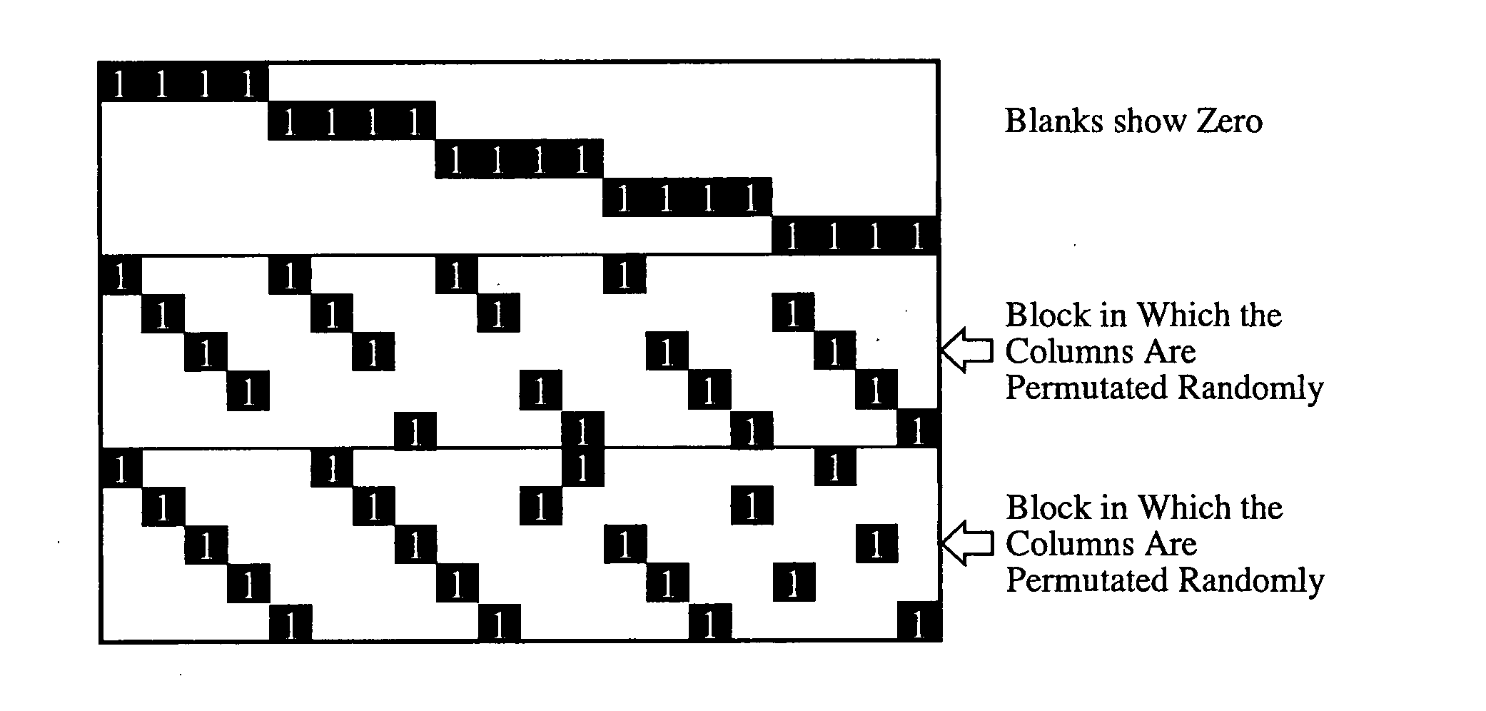
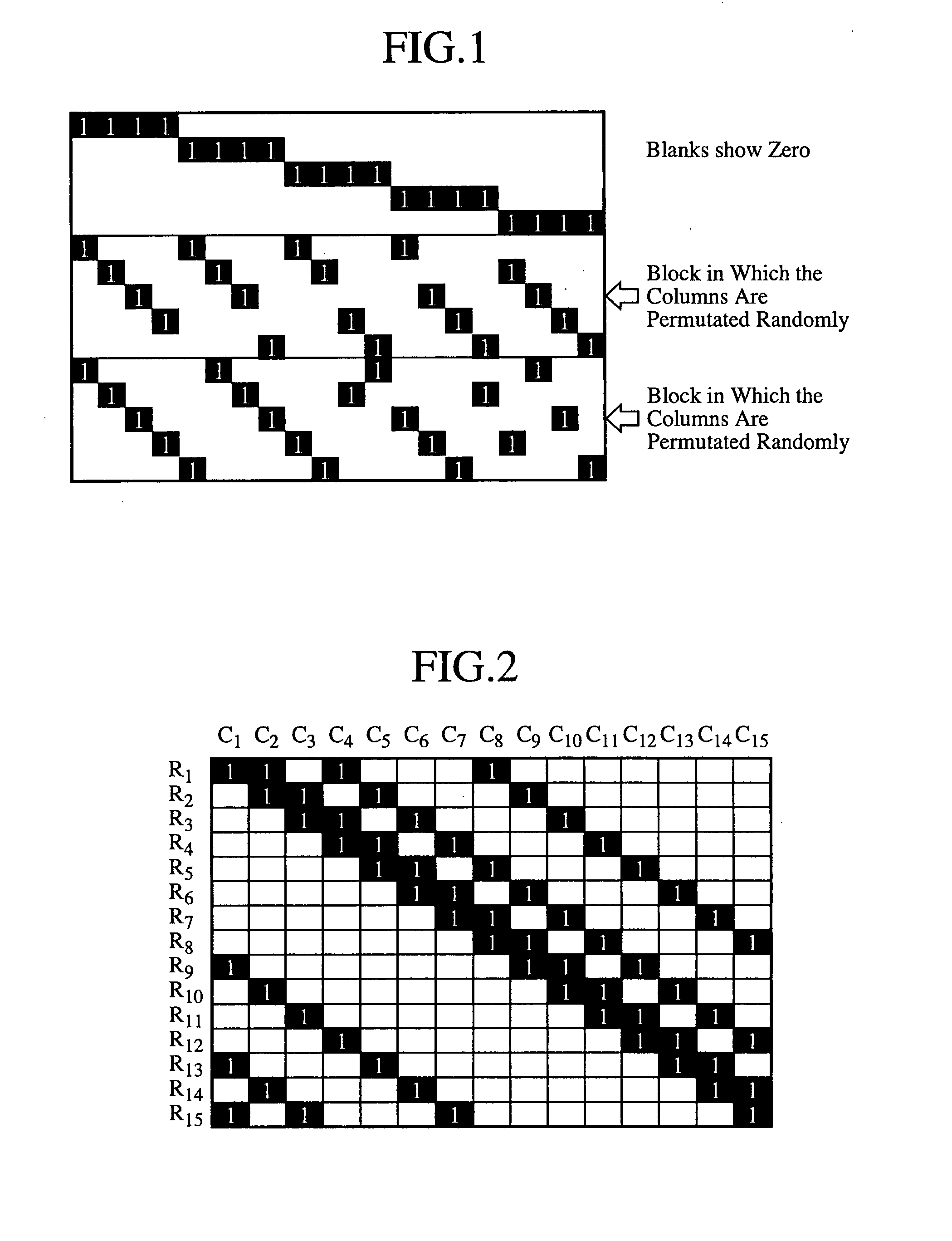
However, because there is no predetermined rule in this random permutation, a search which requires much time to conduct using a computer must be performed in order to find out a code having better characteristics.
A problem with prior art check matrix generation methods for LDPC codes which are practiced as mentioned above is that in most cases a minimum cycle (referred to as an inner diameter) of a check matrix is about 6 (in the case of FIGS. 2 and 3, it is 6), the Hamming distance of the code word increases with increase in the cycle of the check matrix, and the error correction capabilities of the prior art check matrix generation methods are inadequate from the viewpoint of general analysis results which usually provide good characteristics when using the Sum-product decoding method.

Method used


Image

  • Check Matrix Generating Apparatus and Communication Apparatus
  • Check Matrix Generating Apparatus and Communication Apparatus
  • Check Matrix Generating Apparatus and Communication Apparatus

Examples


embodiment 1

[0047]First, before a check matrix generation method for LDPC codes according to this embodiment 1 is explained, the position of an encoder and a decoder which use a generated check matrix for LDPC codes, and a prior art check matrix generation method for “Irregular-LDPC codes” will be explained.

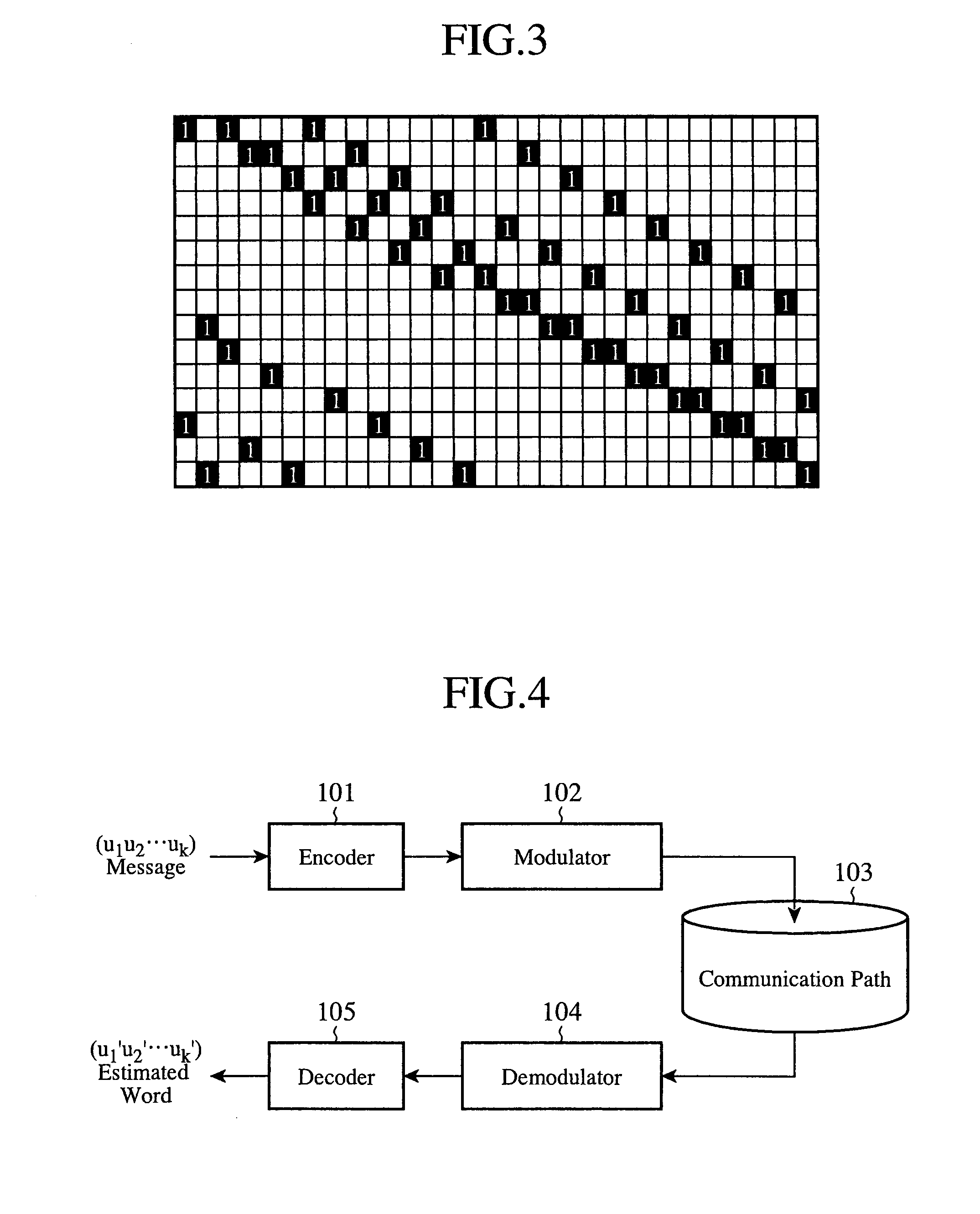
[0048]FIG. 4 is a block diagram showing the structure of an LDPC coding / decoding system. As shown in FIG. 4, a communication apparatus on a transmit side of the system includes an encoder 101 and a modulator 102, while a communication apparatus on a receive side of the system includes a demodulator 104 and a decoder 105. Hereafter, a flow of coding and decoding in a case of using a generated check matrix for LDPC codes will be explained.

[0049]The communication apparatus on the transmit side of the system uses a check matrix H generated by an LDPC code check matrix generating apparatus, as will mentioned below. The encoder 101 calculates a generator matrix G on the basis of the following cond...

embodiment 2

[0147]Next, a method of generating a check matrix for RC (Rate compatible)-LDPC codes, which is an extension to the method according to embodiment 1 and which is compatible at two or more coding rates (the information length does not vary, but only the coding rate varies).

[0148]FIG. 7 is a block diagram showing the structure of a check matrix generating apparatus for LDPC codes in accordance with embodiment 2 of the present invention. This check matrix generating apparatus is provided with an information length, coding rate and maximum column degree input unit 21, a pseudo-random-number permutation matrix parameter calculating unit 22, a pseudo-random-number permutation matrix generating unit 23, a degree distribution optimization parameter, calculating unit 24, a degree distribution optimizing unit 25, and a check matrix generating unit 26. This check matrix generating apparatus can be mounted in each of the communication apparatus on the transmit side of the system shown in FIG. 4...

embodiment 3

[0188]FIG. 10 is a block diagram showing the structure of a check matrix generating apparatus for LDPC codes in accordance with embodiment 3 of the present invention. This check matrix generating apparatus is provided with an information length, coding rate and maximum column degree input unit 31, a pseudo-random-number permutation matrix parameter calculating unit 32, a pseudo-random-number permutation matrix generating unit 33, a degree distribution optimization parameter calculating unit 34, a degree distribution optimizing unit 35, and a check matrix generating unit 36. This check matrix generating apparatus can be mounted in each of the communication apparatus on the transmit side of the system shown in FIG. 4 and that on the receive side of the system so that they can output generated check matrices to the encoder 101 and decoder 105, respectively. As an alternative, the check matrix generating apparatus can be mounted outside each of the communication apparatus on the transmi...


PUM


Abstract

A check matrix generating apparatus calculates a parameter for pseudo-random-number permutation matrices using a predetermined information length, a coding rate, and a maximum column degree, generates the pseudo-random-number permutation matrices from the calculated parameter for the pseudo-random-number permutation matrices by using a pseudo-random-number sequence and a Latin square matrix, determines, as a parameter, a combination of degree distributions which can be adopted for optimization of a degree distribution of generation of a check matrix which can be formed with the pseudo-random-number permutation matrices, using the predetermined information length, coding rate, and maximum column degree, optimizes the degree distribution of generation of a check matrix under a restriction condition based on the determined combination of degree distributions which can be adopted, and arranges the generated pseudo-random-number permutation matrices according to the optimized degree distribution of generation of the check matrix so as to generate the check matrix for low-density parity-check codes.

Description

FIELD OF THE INVENTION[0001]The present invention relates to a check matrix generating apparatus which adopts a low-density parity-check (LDPC: Low-Density Parity-Check) code as an error correcting code, and a communication apparatus equipped with this check matrix generating apparatus. More particularly, it relates to a check matrix generating apparatus which can search for a deterministic check matrix for LDPC codes having stable characteristics, and a communication apparatus equipped with this check matrix generating apparatus.BACKGROUND OF THE INVENTION[0002]Hereafter, a prior art check matrix generation method for LDPC codes will be explained. In a prior art LDPC coding / decoding system, a communication apparatus on a transmit side of the system is provided with an encoder and a modulator, and a communication apparatus on a receive side of the system is provided with a demodulator and a decoder. Hereafter, a flow of coding and decoding at the time of using LDPC codes will be exp...

Claims


Application Information

Patent Timeline
IPC IPC(8): G01R31/28
CPCH03M13/033H03M13/1148H03M13/6393H03M13/118H03M13/116
Inventor MATSUMOTO, WATARU
Owner MITSUBISHI ELECTRIC CORP
Learn More