Line system for an aircraft

a line system and aircraft technology, applied in the field of aircraft line systems, can solve the problems of high cost and personnel expenditure, difficult insertion of lines into existing cable bundles, and difficulty in implementing cabling modifications

Active Publication Date: 2008-08-07
AIRBUS OPERATIONS GMBH
View PDF38 Cites 79 Cited by
  • Summary
  • Abstract
  • Description
  • Claims
  • Application Information

AI Technical Summary

Benefits of technology

[0016]In fiberglass-reinforced composite components, the lines may be used on one hand for mechanical reinforcement of the resin matrix and on the other hand for relaying information. Separate insulation of the optical lines is then no longer necessary. The cabling and / or the line system according to the present invention has, inter alia, the advantage that cable retainers for fixing the position of the cable bundles are no longer necessary, so that expenses for mounting is reduced. Furthermore, cable binders for forming cable bundles may be dispensed with without a replacement, which significantly reduces the mounting effort.
[0019]Because of the low weight and the small spatial dimensions, multiple optical or electrical reserve lines may additionally be easily provided, which are used for repair purposes and / or changes of the circuitry. Required changes on the line system or the cabling of the airplane may be performed easily, for example, by changing over from one line to a reserve line. In addition, a high fault tolerance and redundancy of the line system is achieved.
[0021]In this way, the lines may be integrated in the assemblies before the assemblies are joined together, so that the complex line guiding typically required for an aircraft may be implemented significantly more simply than with a conventional wiring construction.
[0032]The support layer, which is preferably implemented as electrically insulating, allows, for example, the application of electrical lines in the form of printed conductors even on assemblies made of an electrically conductive material without problems. This is for example the case with shells being formed by aluminum alloy sheets in a conventional method of manufacturing. The line system according to the present invention may thus be employed in the scope of the currently typical shell manufacturing method using aluminum sheets, and there are no considerable changes of the manufacturing process necessary.

Problems solved by technology

In addition, the cable bundles may only be manually introduced, laid, and fixed in position in the aircraft structure with a high expenditure in cost and personnel.
Modifications in the cabling may currently be implemented only with difficulty, because in certain circumstances individual lines must be localized in the cable bundles to remove them from the bundle and possibly replace them by alternative lines.
The insertion of lines into an existing cable bundle is also complicated, because in this case the cable bundle must also be opened and subsequently bound together again.
In addition, there is always a risk that chafing points will form between the individual lines in the cable bundle, which result in an impairment of the mechanical integrity of the line insulation and may only be detected with difficulty.
Kinks, disconnections, short-circuits, or cable fires may be caused in this way.
In this case, the support layer is not necessarily implemented as electrically insulating.

Method used


Image

  • Line system for an aircraft
  • Line system for an aircraft
  • Line system for an aircraft

Examples


Embodiment Construction

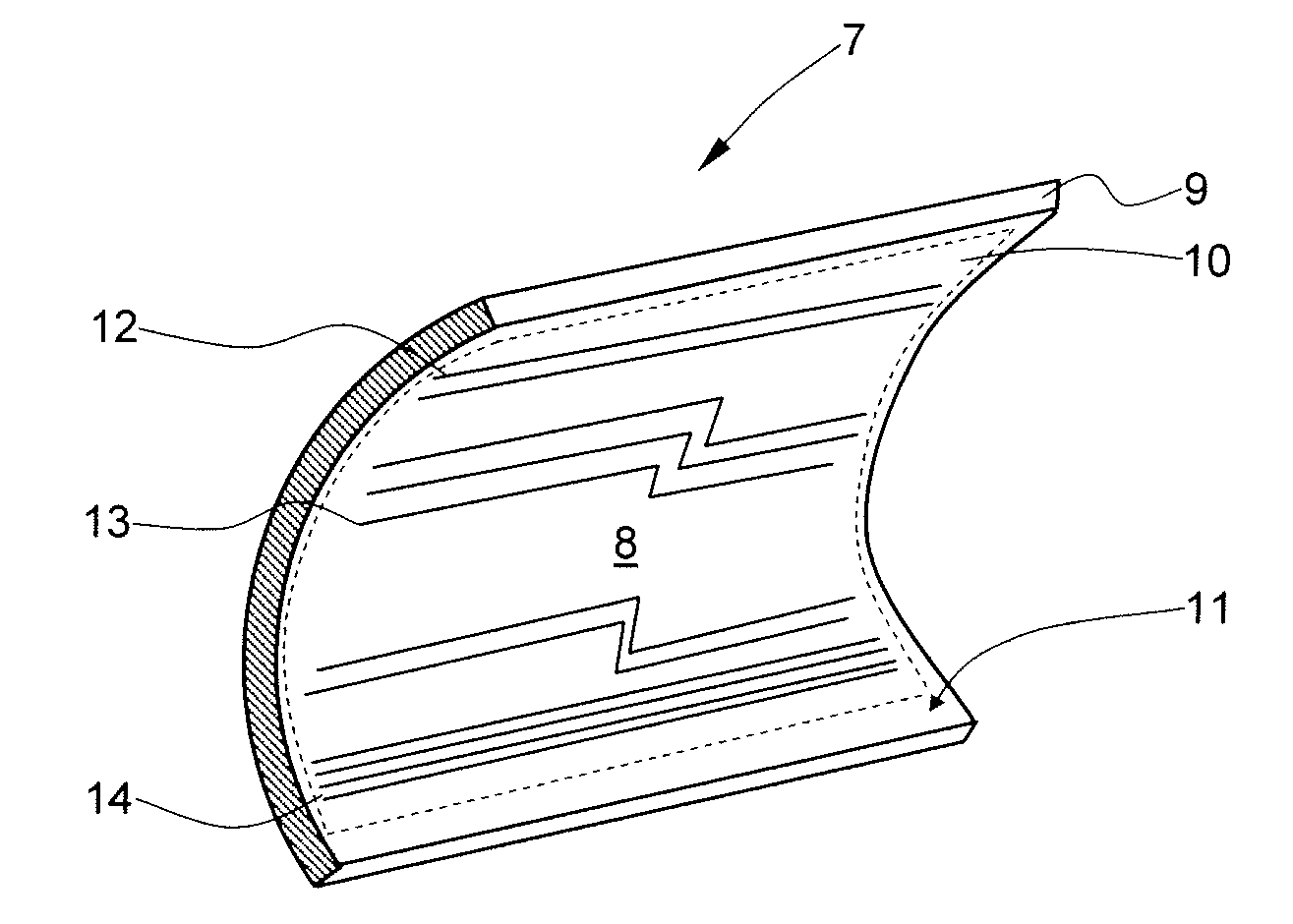
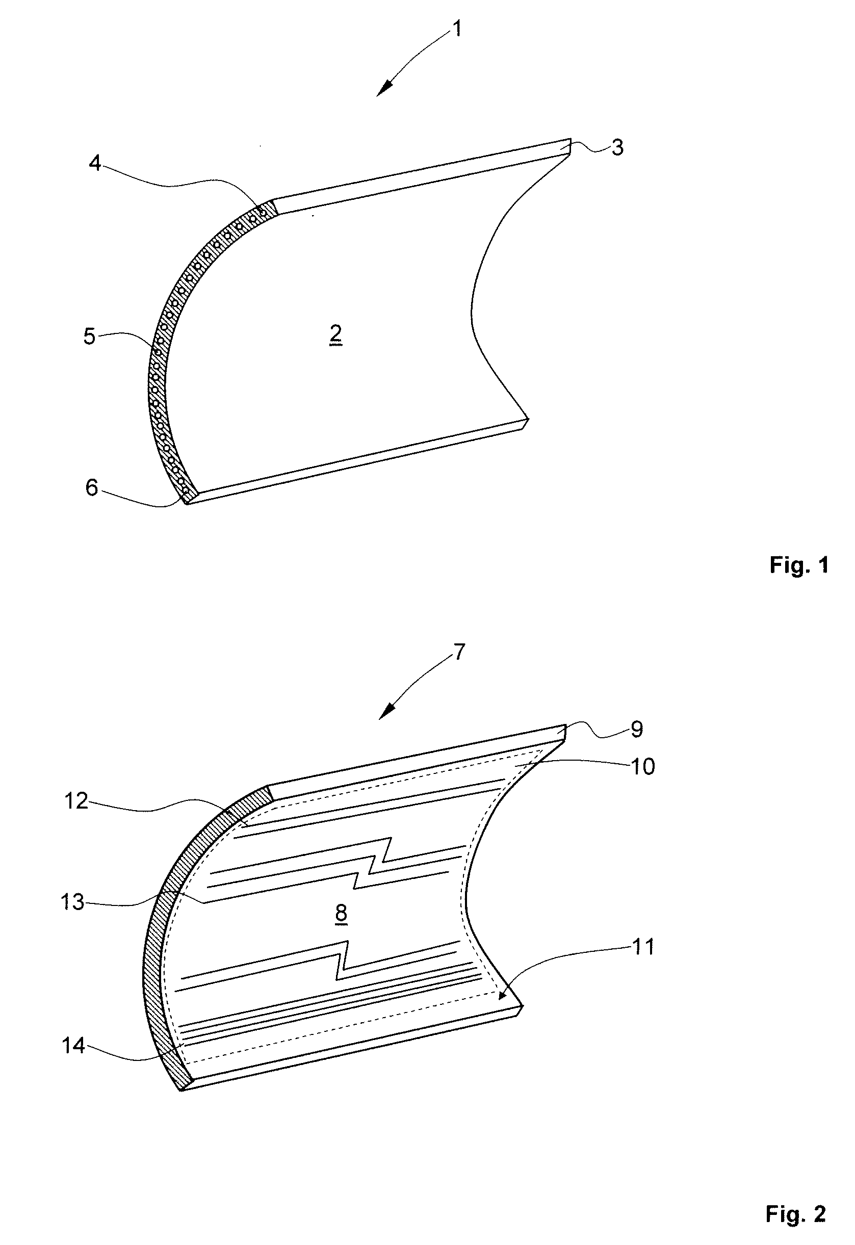
[0043]FIG. 1 shows a section through an assembly having a line system integrated directly in the structure.

[0044]The assembly 1 is a side shell 2 for forming a fuselage section (so-called “barrel”) (not shown) in the exemplary embodiment shown. The fuselage section may be assembled with a further side shell, a top shell, a bottom shell, and at least one floor frame to form a complete fuselage section, for example. A complete fuselage cell for an airplane is formed from multiple fuselage sections arrayed one behind another and permanently connected to one another.

[0045]The side shell 2 is formed using a fiber-reinforced plastic material 3, for example, a carbon-fiber-reinforced epoxy resin. Multiple electrical lines are laid directly in the fiber-reinforced composite material 3, of which only the electrical lines 4 through 6 are provided with a reference numeral for the sake of better overview of the drawing. The electrical lines 4 through 6 may be embedded in the resin matrix of the...


PUM


Abstract

A line system for an aircraft, in particular an airplane, having multiple assemblies, in particular multiple fuselage sections of a fuselage cell and multiple wing shells, the line system including multiple lines for transmitting power and / or information, wherein the lines are integrated on and / or in a support layer, the support layer being situated on and / or in the shell-shaped assemblies.

Description

BACKGROUND[0001]1. Field[0002]The disclosed embodiments relate to a line system for an aircraft, in particular an airplane, having multiple lines, the aircraft comprising multiple assemblies, in particular multiple fuselage sections of a fuselage cell and multiple wing shells.[0003]2. Brief Description of Related Developments[0004]Shell construction finds widespread use in aircraft construction. For this purpose, pre-finished fuselage cells are assembled into so-called “barrels” (complete fuselage sections) to produce a fuselage cell. The fuselage shells for forming fuselage sections may be formed using aluminum sheets, for example. The fuselage sections are subsequently arrayed with one another to form the fuselage cell and are thereafter attached to one another, for example, by conventional rivet connections. Corresponding methods are used in the production of airfoils, elevator units, rudder units, and landing flaps or the like.[0005]Advantageously also a shell construction may b...

Claims


Application Information

Patent Timeline
Patent Type & Authority Applications(United States)
IPC IPC(8): B64C1/00
CPCB64C1/12G02B6/3817G02B6/3897H02G3/36G02B6/4403H02G3/30G02B6/43
Inventor DANNENBERG, HEIKO
Owner AIRBUS OPERATIONS GMBH
Why Eureka
Try Eureka