Method for adjusing tuning circuit and receiver circuit

a receiver circuit and tuning circuit technology, applied in continuous tuning, discontnuous tuning with seperate pre-tuned circuits, resonance circuit tuning, etc., can solve the problems of large storage capacity of non-volatile memory, the coil may not be put in an ic, and the time required to adjust the pieces of aforementioned tuning data, so as to reduce the load borne

Inactive Publication Date: 2008-08-07
SONY CORP
View PDF2 Cites 9 Cited by
  • Summary
  • Abstract
  • Description
  • Claims
  • Application Information

AI Technical Summary

Benefits of technology

[0017]According to an embodiment of the present invention, a tracking adjustment process can be carried out on the basis of typically two tuning frequencies so that the process can be completed in a short period of time. In addition, the amount of data obtained as a result of the tracking adjustment process as control data for tuning is extremely small, making it possible to make use of a non-volatile memory having a small storage capacity as a memory used for storing the control data for tuning.
[0018]On top of that, even in the case of a receiver for receiving broadcasts by dividing a broad band of reception into a number of sub-bands, the tracking adjustment process can be carried ou

Problems solved by technology

However, a coil may not be put in an IC.
In this case, however, it takes much time to adjust the pieces of aforementioned tuning data D2 and D4.
In addition, the non-volatile memory needs a large storage capacity.
In the case of such a receive

Method used


Image

  • Method for adjusing tuning circuit and receiver circuit
  • Method for adjusing tuning circuit and receiver circuit
  • Method for adjusing tuning circuit and receiver circuit

Examples


Embodiment Construction

[1]: First Typical Tuning Circuit

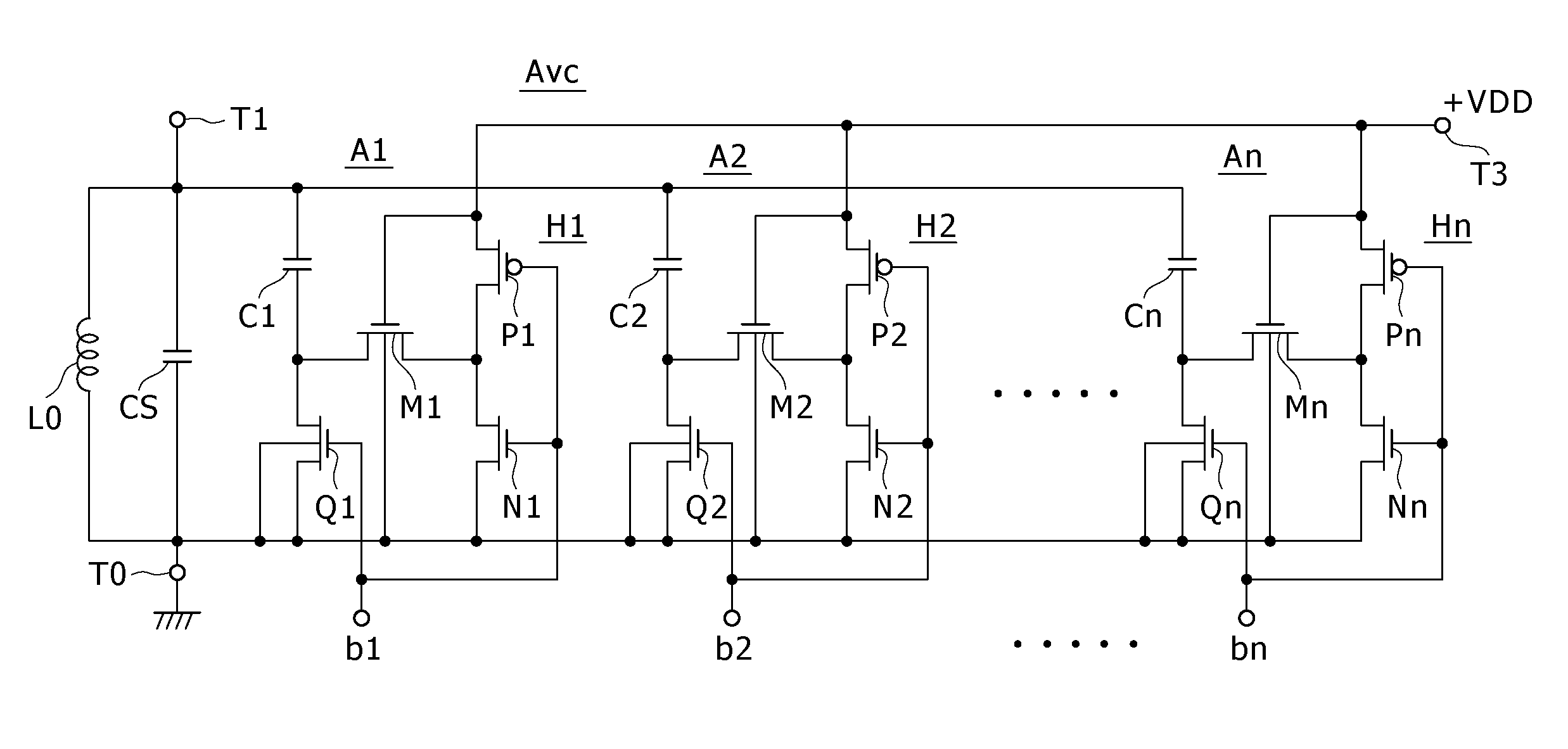
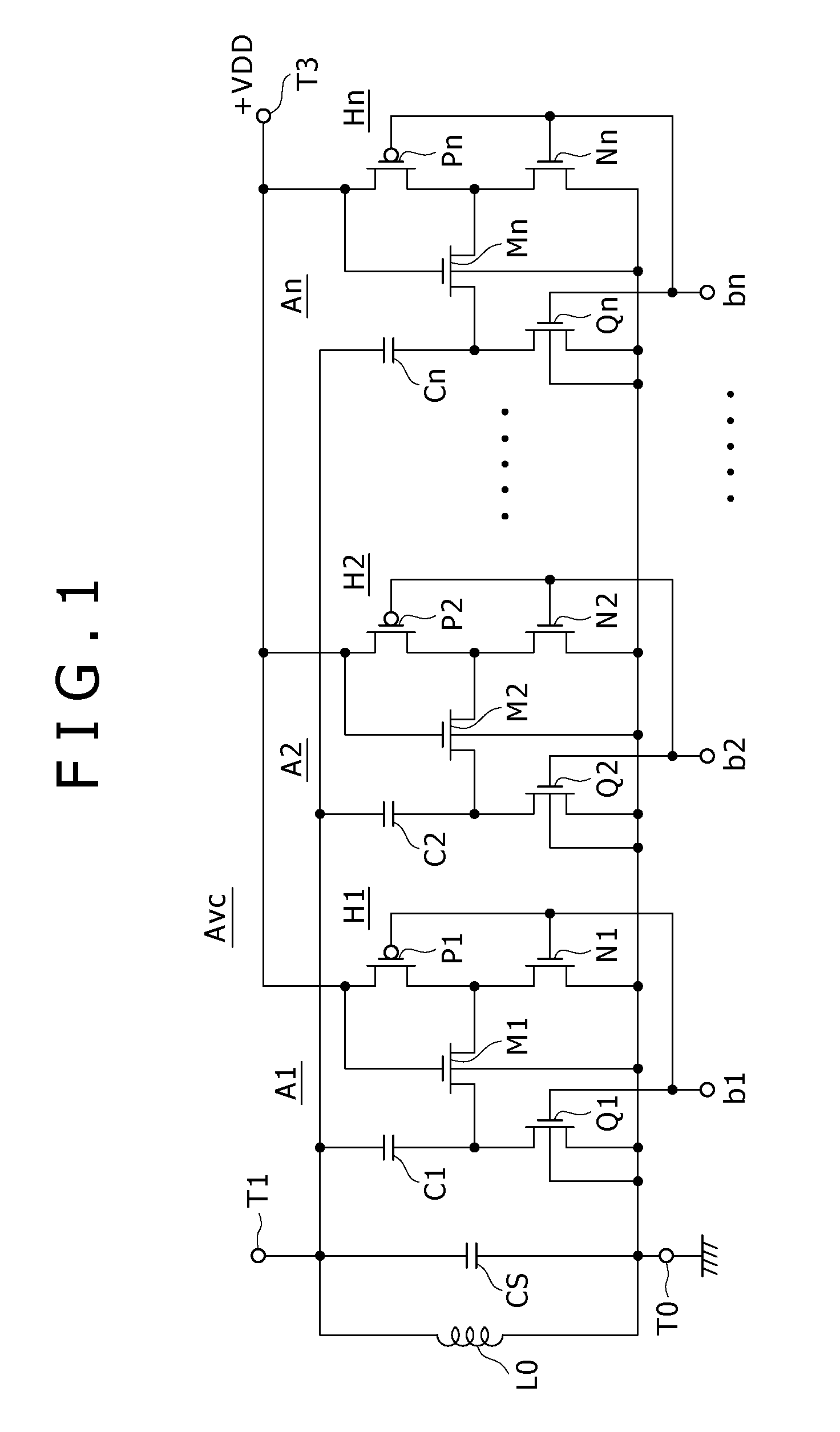
[0031]FIG. 1 is a diagram showing a typical tuning circuit, the tuning frequency of which is to be adjusted by a tuning-frequency adjustment method according to the present invention. This tuning circuit can be used as the antenna tuning circuit 2 and / or the inter-stage tuning circuit 4. The tuning circuit shown in FIG. 1 includes an external tuning coil L0 and a variable-capacitance circuit AVC having n capacitance circuits A1 to An. The capacitance of the variable-capacitance circuit AVC is changed by applying n digital control bits b1 to bn to the n capacitance circuits A1 to An in order to control the tuning frequency. Hereinafter, a subscript i in the range 1 to n.

[0032]As shown in FIG. 1, the external tuning coil L0 is connected between a terminal T0 on the ground side and a terminal T1 on the hot side. Connected to the ground, the terminal T0 is referred to hereafter as the ground terminal T0. It is to be noted that notation CS used in FIG. 1 ...


PUM


Abstract

Disclosed herein is a method for adjusting the tuning frequency of a tuning circuit, which is implemented as a parallel circuit of a coil and series circuits Ai each including a capacitor Ci and a switch device Qi (i=one to n, where n denotes an integer at least equal to two), by varying the tuning frequency through control to turn on and off the switch devices Qi in accordance with control data bi, the method for adjusting the tuning frequency of a tuning circuit including the steps of: finding control data bi for a desired tuning frequency from control data bi for a tuning frequency equal to a first frequency and control data bi for a tuning frequency equal to a second frequency; and applying the control data bi found for the desired tuning frequency to the switch devices Qi.

Description

CROSS REFERENCES TO RELATED APPLICATIONS[0001]The present invention contains subject matter related to Japanese Patent Application JP 2007-025200 filed in the Japan Patent Office on Feb. 5, 2007, the entire contents of which being incorporated herein by reference.BACKGROUND OF THE INVENTION[0002]1. Field of the Invention[0003]The present invention relates to a method for adjusting a tuning circuit and a receiver circuit.[0004]2. Description of the Related Art[0005]A high-frequency circuit employed in a receiver adopting a synthesizer method has a configuration like one shown in FIG. 10. As shown in the figure, broadcast signals received by an antenna 1 are supplied to an antenna tuning circuit 2 for selecting a signal SRX having the frequency of a desired broadcast. The antenna tuning circuit 2 supplies the selected signal SRX to a mixer circuit 5 by way of a high-frequency amplifier 3 and an inter-stage tuning circuit 4. In the mean time, a VCO (Voltage-Controlled Oscillator) 61 ge...

Claims


Application Information

Patent Timeline
IPC IPC(8): H03J3/20
CPCH03J2200/10H03J1/0008
Inventor OKANOBU, TAIWA
Owner SONY CORP
Why Eureka
Try Eureka