Electric fuse circuit available as one time programable memory

a one-time programable memory and fuse circuit technology, applied in static storage, electrical equipment, instruments, etc., can solve the problems of significant affecting manufacturing costs, tddb degradation progress, etc., and achieve the effect of reducing the area of the electric fuse circuit, reducing the area of the circuit, and more inexpensive otp memory

Active Publication Date: 2008-08-07
PANASONIC SEMICON SOLUTIONS CO LTD
View PDF19 Cites 17 Cited by
  • Summary
  • Abstract
  • Description
  • Claims
  • Application Information

AI Technical Summary

Benefits of technology

[0083]As described above, the present invention allows the logic transistor to be used as a switch transistor (first switch transistor) for feeding a current required to set the fuse element to the fused state. This enables a reduction in the area of the electric fuse circuit, providing a more inexpensive OTP memory.
[0084]The electric fuse circuit according to the present invention allows a reduction in the area of the circuit by enabling the logic transistor to be used as the switch transistor for feeding the current required to set the fuse element to the fused state. The present invention is thus useful if the electric fuse circuit is used as a fuse element for RAM redundancy relief. Furthermore, the electric fuse circuit according to the present invention is used as an OTP memory utilized in, for example, a system LSI chip having an ID function for allowing system settings inherent in equipment to be recorded therein or a secure ID function for protecting information, a semiconductor chip in which a lot number, a chip coordinate position, the results of inspections during a shipping process, and the like are recorded, to provide a chip ID function for enabling tracing such as failure analysis, or an IC tag intended for tracking such as distribution management or identification of aircraft luggage.

Problems solved by technology

First, 500 to 1,000 fuse elements for RAM redundancy relief are mounted on each chip. Thus, an instantaneous carrying current of about 10 to 30 A is required to fuse the 1,000 electric fuse elements at a time. It is difficult for the existing general-purpose tester to concentrate a current of 10 to 30 A inside an LSI chip, resulting in the need for a dedicated tester. Furthermore, if for example, 1,000 independent electric fuse circuits are mounted in a system LSI and electric fuse elements are sequentially programmed one by one, a large number of control terminals are required. For example, if each circuit has four control terminals, 4,000 control terminals are required but cannot be mounted in the system LSI.
Thus, disadvantageously, TDDB degradation progresses.
In spite of the possibility of a rewriting operation, a nonvolatile memory which requires a separate process similarly to flash memories and which is likely to be developed behind the most advanced process by several generations cannot meet the needs utilizing the most advanced process, in view of timing for the introduction, manufacturing costs, and the like.
However, as previously described, the configuration of the conventional electric fuse circuit disadvantageously has a great area impact on the chip, significantly affecting manufacturing costs.

Method used


Image

  • Electric fuse circuit available as one time programable memory
  • Electric fuse circuit available as one time programable memory
  • Electric fuse circuit available as one time programable memory

Examples


embodiment 1

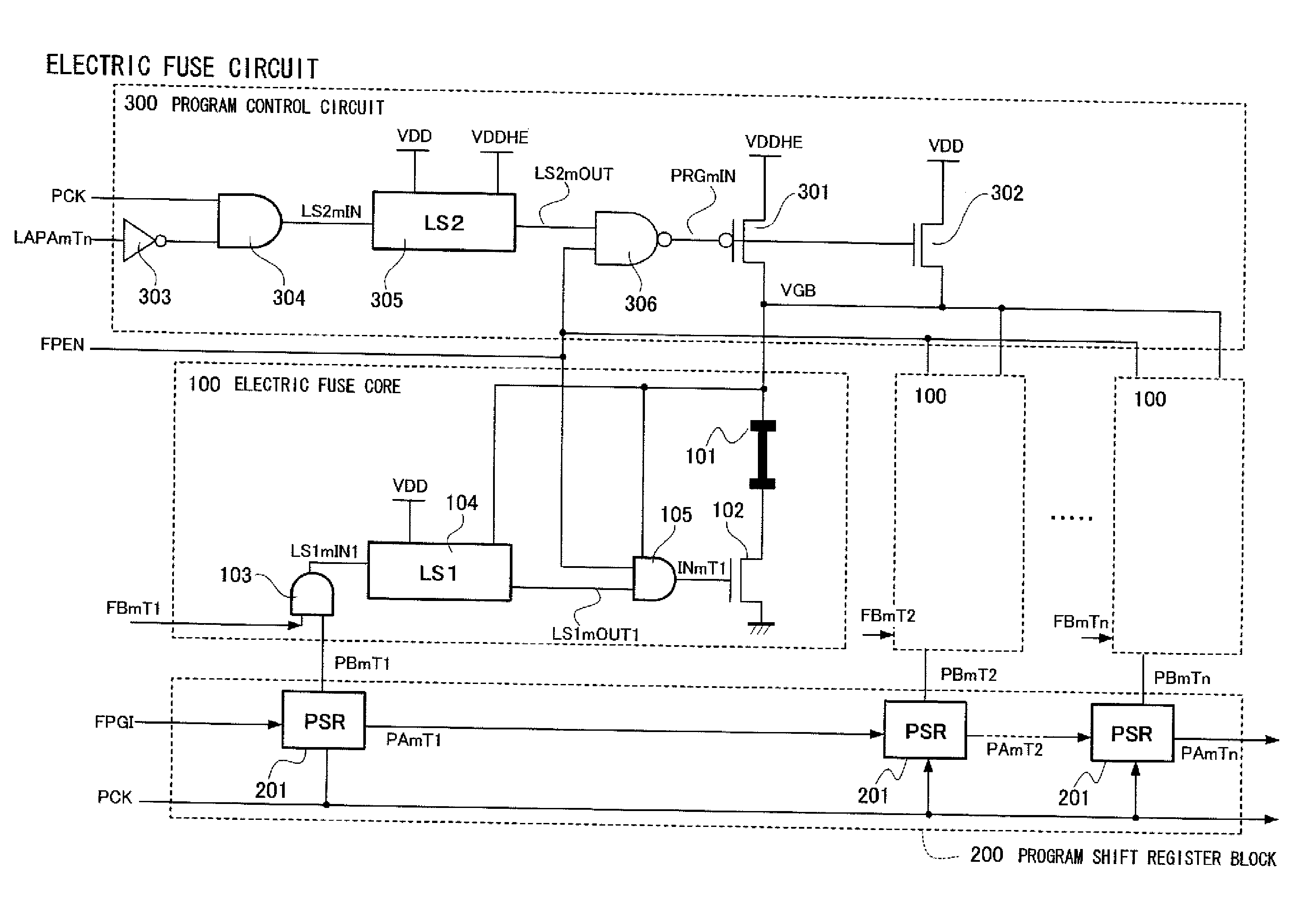
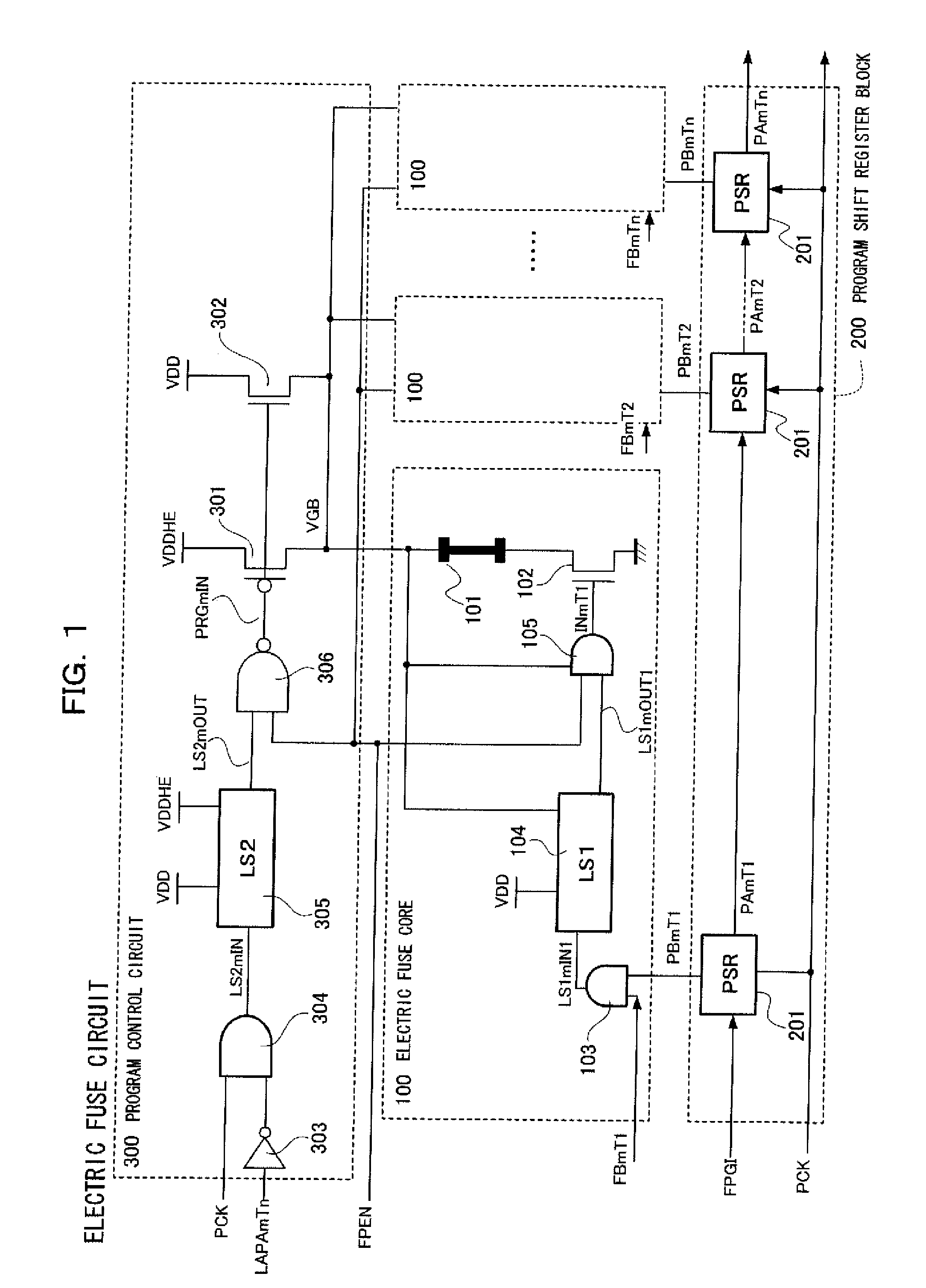
[0098]An electric fuse circuit according to Embodiment 1 of the present invention will be described below with reference to the drawings. During a programming operation, the electric fuse circuit programs a fuse element by passing or not passing a current through the fuse element to set the fuse element to one of a fused state and a non-fused state.

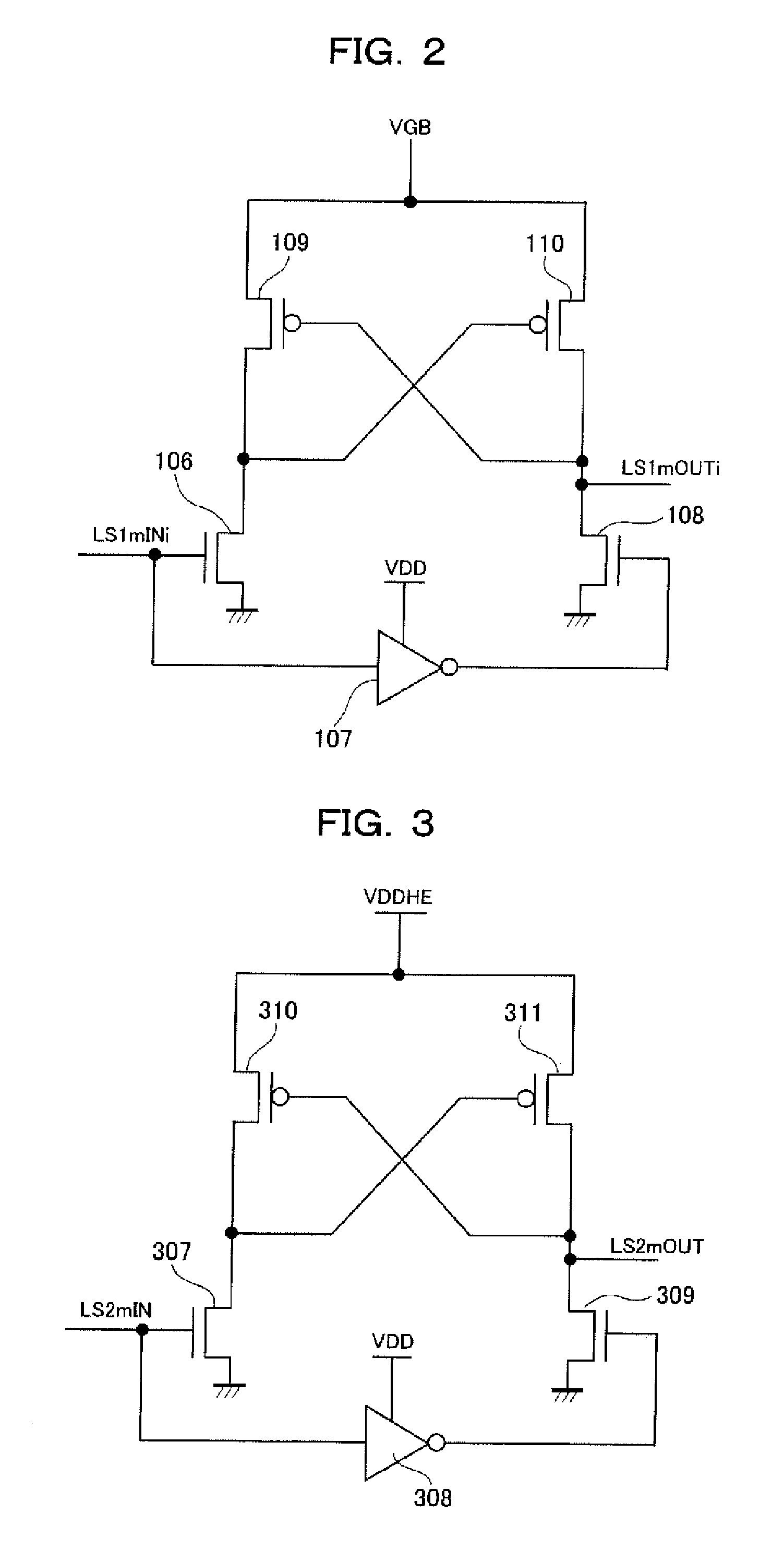
[0099]FIG. 1 is a circuit diagram showing the configuration of the electric fuse circuit according to Embodiment 1. The same members as described with reference to FIGS. 11 and 12 are denoted by the same reference numerals and will thus not be described. As shown in FIG. 1, the electric fuse circuit is made up of a plurality of (n) electric fuse cores 100, a program shift register block 200 having a plurality of (n) stages, and a program control circuit 300. The program shift register block 200 is the same as that described with reference to FIGS. 11 and 12 and will thus not be described.

[0100]First, the electric fuse core 100 will be des...

embodiment 2

[0169]An electric fuse circuit according to Embodiment 2 of the present invention will be specifically described with reference to the drawings. FIG. 5 is a circuit diagram showing the configuration of the electric fuse circuit according to Embodiment 2. The same members as those described with reference to FIGS. 1 to 3, 11, and 12 are denoted by the same reference numerals and will thus not be described.

[0170]As is the case with Embodiment 1, the electric fuse circuit is made up of a plurality of (n) electric fuse cores 100, a program shift register block 200 having a plurality of (n) steps, and a program control circuit 300. The program shift register block 200 is the same as that described with reference to FIGS. 11 and 12 and will thus not be described. Furthermore, the electric fuse core 100 is the same as that described with reference to FIGS. 1 and 2 except that an AND circuit 111 corresponding to the AND circuit 105, shown in FIG. 1, uses the signal VGB as a power source. Th...

embodiment 3

[0194]An electric fuse circuit according to Embodiment 3 of the present invention will be specifically described with reference to the drawings. FIG. 7 is a circuit diagram showing the configuration of the electric fuse circuit according to Embodiment 3. The same members as those described with reference to FIGS. 1 to 3, 5, 11, and 12 are denoted by the same reference numerals and will thus not be described.

[0195]As is the case with Embodiment 1, the electric fuse circuit is made up of a plurality of (n) electric fuse cores 100, a program shift register block 200 having a plurality of (n) steps, and a program control circuit 300. The program shift register block 200 is the same as that described with reference to FIGS. 11 and 12 and will thus not be described. Furthermore, the program control circuit 300 is the same as that described above in Embodiment 2 and will thus not be described below.

[0196]In Embodiment 3, as in the case of Embodiment 2, the fuse program enable signal FPEN s...


PUM


Abstract

A first transistor is connected in series with one end of a fuse element. A second transistor is connected in series with the other end of the fuse element. A current flows through the fuse element when both the first and second transistors are turned on.

Description

FIELD OF THE INVENTION[0001]The present invention relates to an electric fuse circuit used as an OTP (One Time Programmable) memory.BACKGROUND OF THE INVENTION[0002]Electric fuse circuits haven been implemented which program a fuse element by feeding or not feeding a current through the fuse circuit to fuse or not fuse the fuse element. The electric fuse circuit is widely used in semiconductor integrated circuits (LSI) such as trimming program devices for high-frequency semiconductor devices. The conventional electric fuse circuit is made up of electric fuse elements formed of polysilicon and bipolar transistors each feeding a current required to fuse the corresponding electric fuse element. The bipolar transistor is used to feed a large current of about 1 A (Ampere) to fuse the corresponding electric fuse element.[0003]In recent years, in the field of semiconductor integrated circuits, a technique has been developed which forms a silicide layer on a polysilicon layer to reduce the ...

Claims


Application Information

Patent Timeline
Patent Type & Authority Applications(United States)
IPC IPC(8): G11C17/16
CPCG11C17/18
Inventor SUMI, SHINICHIAGATA, YASUHIROSHIRAHAMA, MASANORIKAWASAKI, TOSHIAKINISHIHARA, RYUJI
Owner PANASONIC SEMICON SOLUTIONS CO LTD
Why Eureka
Try Eureka