Temperature detection circuit

a temperature detection and circuit technology, applied in the direction of pulse manipulation, pulse technique, instruments, etc., can solve the problem of complex correction procedures that are required to accurately detect a temperature, and achieve the effect of accurate detection of a temperatur

Inactive Publication Date: 2008-08-07
DENSO CORP
View PDF13 Cites 20 Cited by
  • Summary
  • Abstract
  • Description
  • Claims
  • Application Information

AI Technical Summary

Benefits of technology

[0008]In view of the above-described problem, it is an object of the present invention to provide a temperature detection circuit for accurately detecting a temperature without a complex correction procedure.

Problems solved by technology

Therefore, complex correction procedures are required to accurately detect a temperature.

Method used


Image

  • Temperature detection circuit
  • Temperature detection circuit
  • Temperature detection circuit

Examples


first embodiment

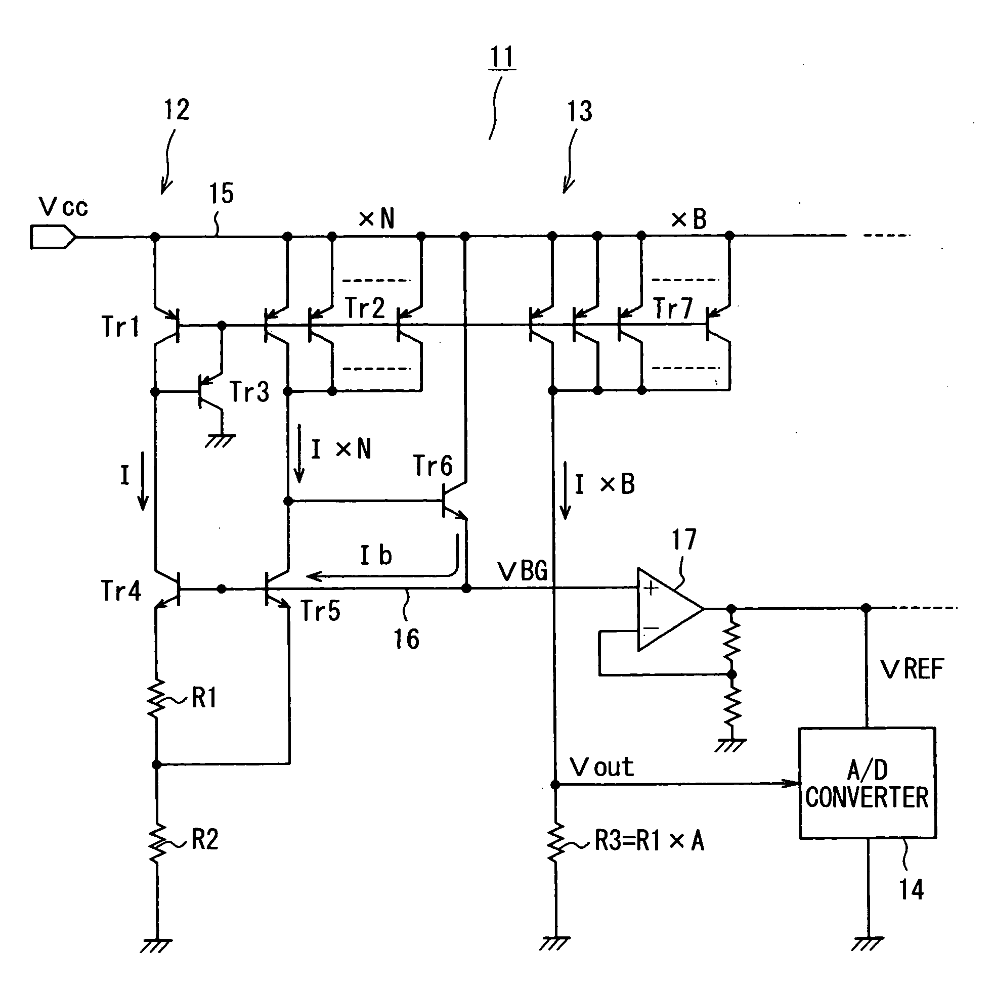
[0026]Referring to FIG. 1, a temperature detection circuit 11 according to a first embodiment of the present invention includes a bandgap reference voltage (VBG) generator 12, a detection output circuit 13, and an analog-to-digital (A / D) converter 14.

[0027]The VBG generator 12 is configured to output a bandgap reference voltage VBG through an output line 16. In the VBG generator 12, PNP transistors Tr1, Tr2 construct a first current mirror circuit. The bases of the transistors Tr1, Tr2 are coupled together, and the emitters of the transistors Tr1, Tr2 are coupled to a power line 15 of a power supply voltage Vcc. The transistors Tr1, Tr2 are designed such that a cell area ratio (i.e., emitter ratio) is set to 1:N, where N is a positive number. Therefore, a first mirror current as a collector current of the transistor Tr2 is N times greater than a bias current I as a collector current of the transistor Tr1. The emitter of PNP transistor Tr3 is coupled to the bases of the transistors T...

second embodiment

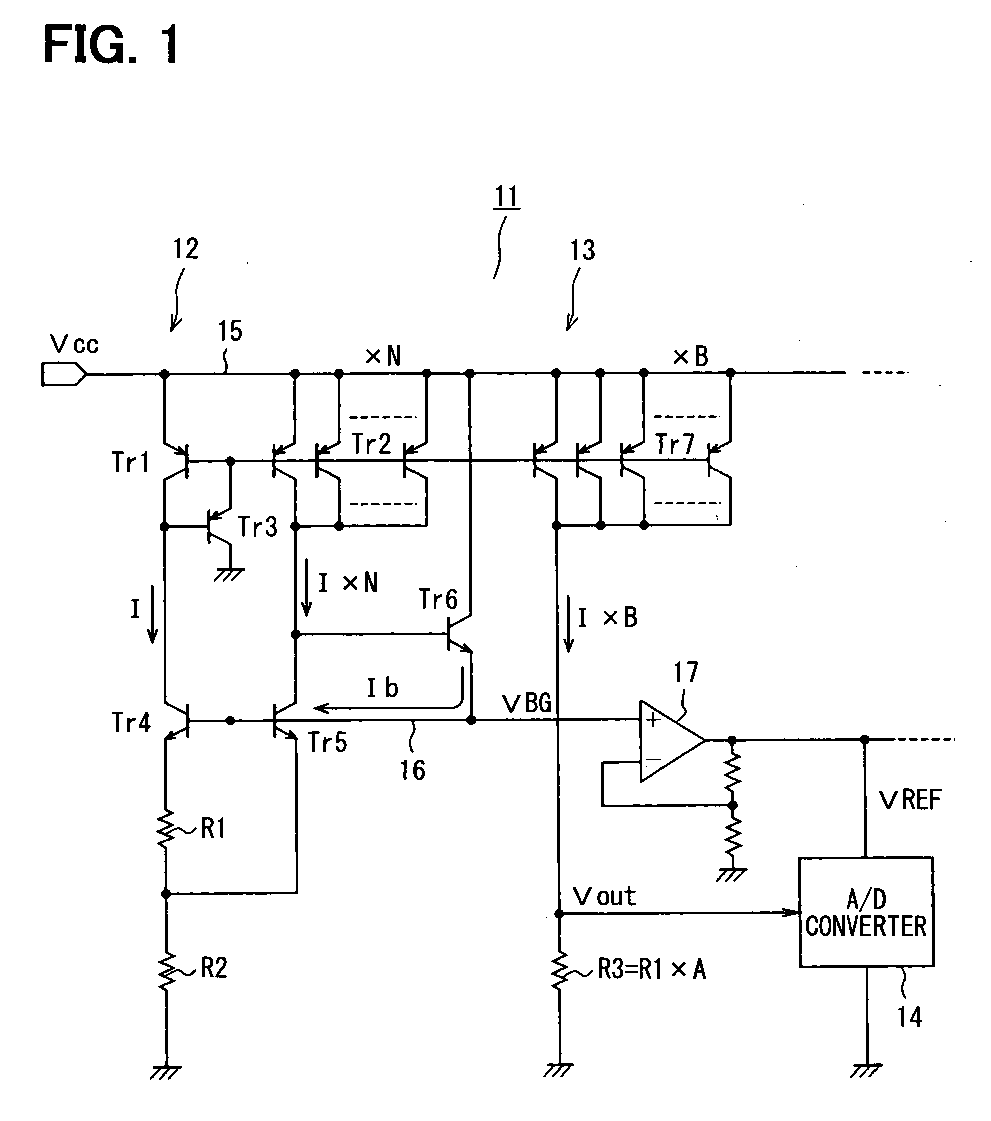
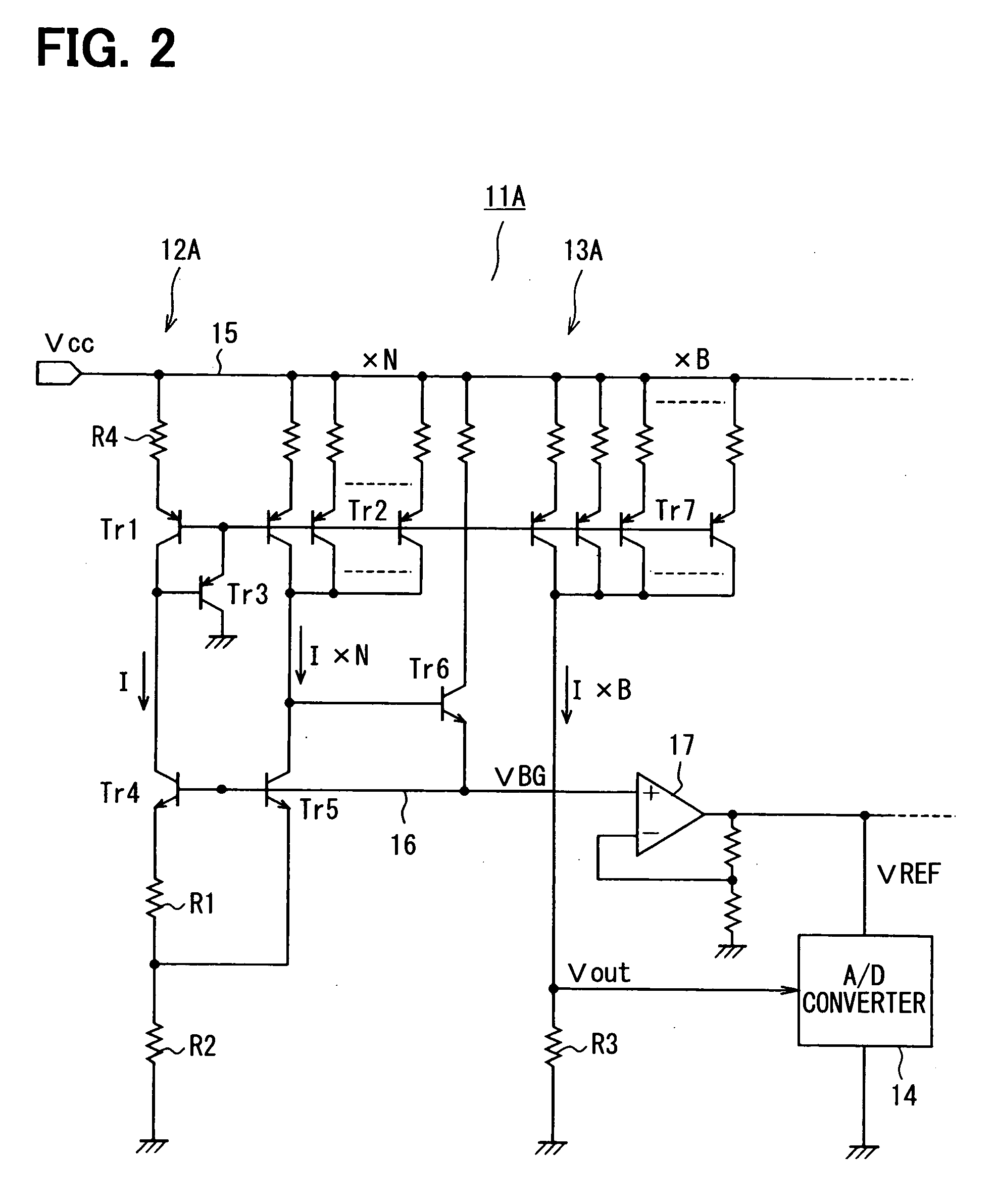
[0039]A temperature detection circuit 11A according to a second embodiment of the present invention is described below with reference to FIG. 2. A difference between the temperature detection circuits 11, 11A is as follows. The temperature detection circuit 11A further includes a resistor R4 coupled between the power line 15 and each emitter of the transistors Tr1, Tr2, Tr7. In such an approach, a mirror ratio N of a first current mirror circuit in a VBG generator 12A and a mirror ratio B of a second current mirror circuit in a detection output circuit 13A can be preciously adjusted so that the temperature detection circuit 11A can more accurately detect a temperature.

third embodiment

[0040]A temperature detection circuit 11B according to a third embodiment of the present invention is described below with reference to FIG. 3. A difference between the temperature detection circuits 11A, 11B is as follows. The temperature detection circuit 11B includes a variable detection resistor R3_V instead of the detection resistor R3. In such an approach, the mirror ratio B of the second current mirror circuit in the detection output circuit 13A can be easily adjusted by changing a resistance of the variable detection resistor R3_V. Thus, the constant slope of C, at which the temperature detection voltage Vout changes lineally with the temperature T, can be easily adjusted using the variable detection resistor R3_V.


PUM

PropertyMeasurementUnit
temperatureaaaaaaaaaa
reference voltageaaaaaaaaaa
thermal voltageaaaaaaaaaa

Abstract

A temperature detection circuit includes a bandgap reference voltage generation circuit, a detection output circuit, and an output conversion circuit. The bandgap reference voltage generation circuit generates a first reference voltage and causes a bias current to flow through a current path to produce a thermal voltage. The current path has a first resistor. The detection output circuit has a second resistor and causes a mirror current of the bias current to flow through the second resistor. The output conversion circuit uses a second reference voltage to convert a voltage drop across the second resistor to a predetermined output form to detect a temperature. The first and second resistors are substantially identical in temperature dependence. The second reference voltage is generated from the first reference voltage.

Description

CROSS REFERENCE TO RELATED APPLICATION[0001]This application is based on and incorporates herein by reference Japanese Patent Applications No. 2007-27958 filed on Feb. 7, 2007 and No. 2007-183211 filed on Jul. 12, 2007.FIELD OF THE INVENTION[0002]The present invention relates to a temperature detection circuit that detects a temperature by using a thermal voltage generated by a bias current flowing in a bandgap reference voltage generation circuit.BACKGROUND OF THE INVENTION[0003]A microcontroller illustrated 1 in FIG. 14 has been disclosed in U.S. Pat. No. 5,619,430 corresponding to JP-A-H10-503611. The microcontroller 1 includes a temperature sensor 2. As illustrated in FIG. 15, the temperature sensor 2 includes a ΔVbe generator 350 and a differential amplifier 352 for generating an output voltage Vout, which is supplied to one input of a multiplexer (MUX) 4 for sampling by a slope analog-to-digital (A / D) converter 3.[0004]The ΔVbe generator 350 includes PNP bipolar transistors 35...

Claims


Application Information

Patent Timeline
Patent Type & Authority Applications(United States)
IPC IPC(8): G01K7/16G05F3/22
CPCG01K7/20G01K7/015
Inventor UEDA, SUSUMU
Owner DENSO CORP
Why Eureka
Try Eureka