Structure and Method for Bonding Two Members, Gas Container and Method for Manufacturing Such Gas Container

a technology for gas containers and structures, applied in the direction of transportation and packaging, mechanical equipment, other domestic objects, etc., can solve the problems of affecting the bonding surface, and affecting the bonding strength of the bonded portion, so as to improve the bonding strength and the position deviation

Inactive Publication Date: 2008-08-07
TOYOTA JIDOSHA KK
View PDF4 Cites 48 Cited by
  • Summary
  • Abstract
  • Description
  • Claims
  • Application Information

AI Technical Summary

Benefits of technology

[0007]Moreover, an object of the present invention is to provide a gas container and a manufacturing method of the gas container capable of appropriately bonding end portions of liner constituting members to each other by laser welding in a state in which this bonded structure of two members is applied to a resin liner of a gas container to suppress a positional deviation between the end portions of the liner constituting members.
[0056]According to these constitutions, in a manufacturing process of the resin liner constituted by bonding the liner constituting members to each other, the end portions of the liner constituting members are engaged with each other by the engagement structure, and the end portions can be irradiated with the laser in this engaged state. In consequence, the positional deviation between the end portions can preferably be suppressed, and the end portions can satisfactorily be bonded to each other by laser welding without using any pressurizing jig or the like. Even after the laser welding, the bonded portion is engaged by the engagement structure in addition to the laser welded portion. Therefore, the strength of the bonded portion can be improved.

Problems solved by technology

Therefore, there is a possibility that abutment of the bonding surfaces deviates during the irradiation with the laser.
In consequence, a bonding defect might be caused.
Needless to say, to solve such a problem of bonding defect, it is considered that a pressurizing jig be prepared for maintaining the contact state between the end portions, but this incurs much cost and additionally becomes complicated.

Method used


Image

  • Structure and Method for Bonding Two Members, Gas Container and Method for Manufacturing Such Gas Container
  • Structure and Method for Bonding Two Members, Gas Container and Method for Manufacturing Such Gas Container
  • Structure and Method for Bonding Two Members, Gas Container and Method for Manufacturing Such Gas Container

Examples


first embodiment

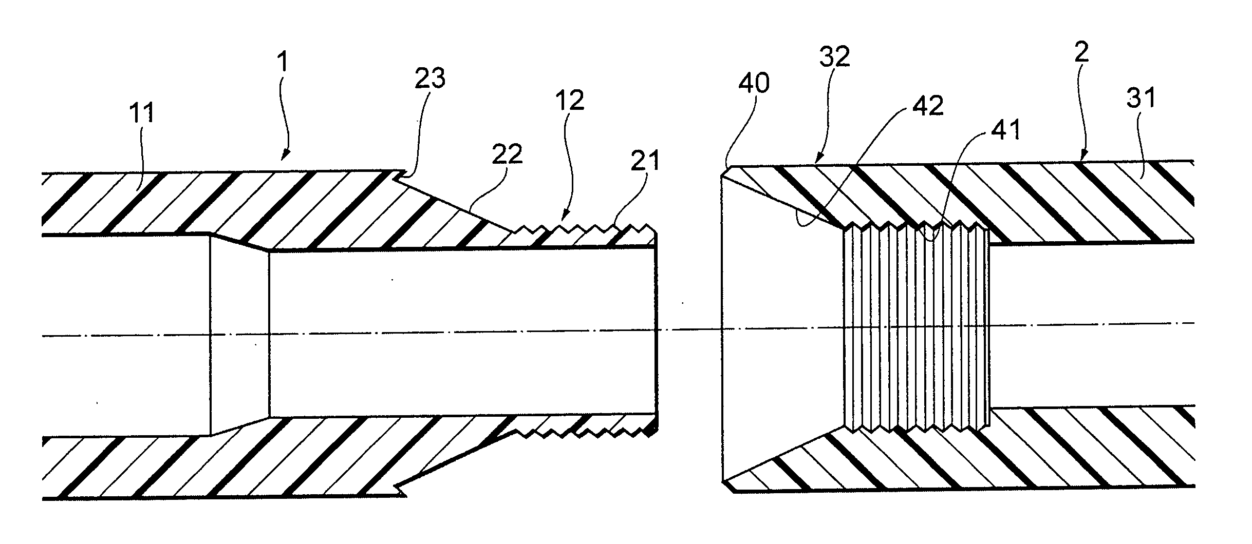
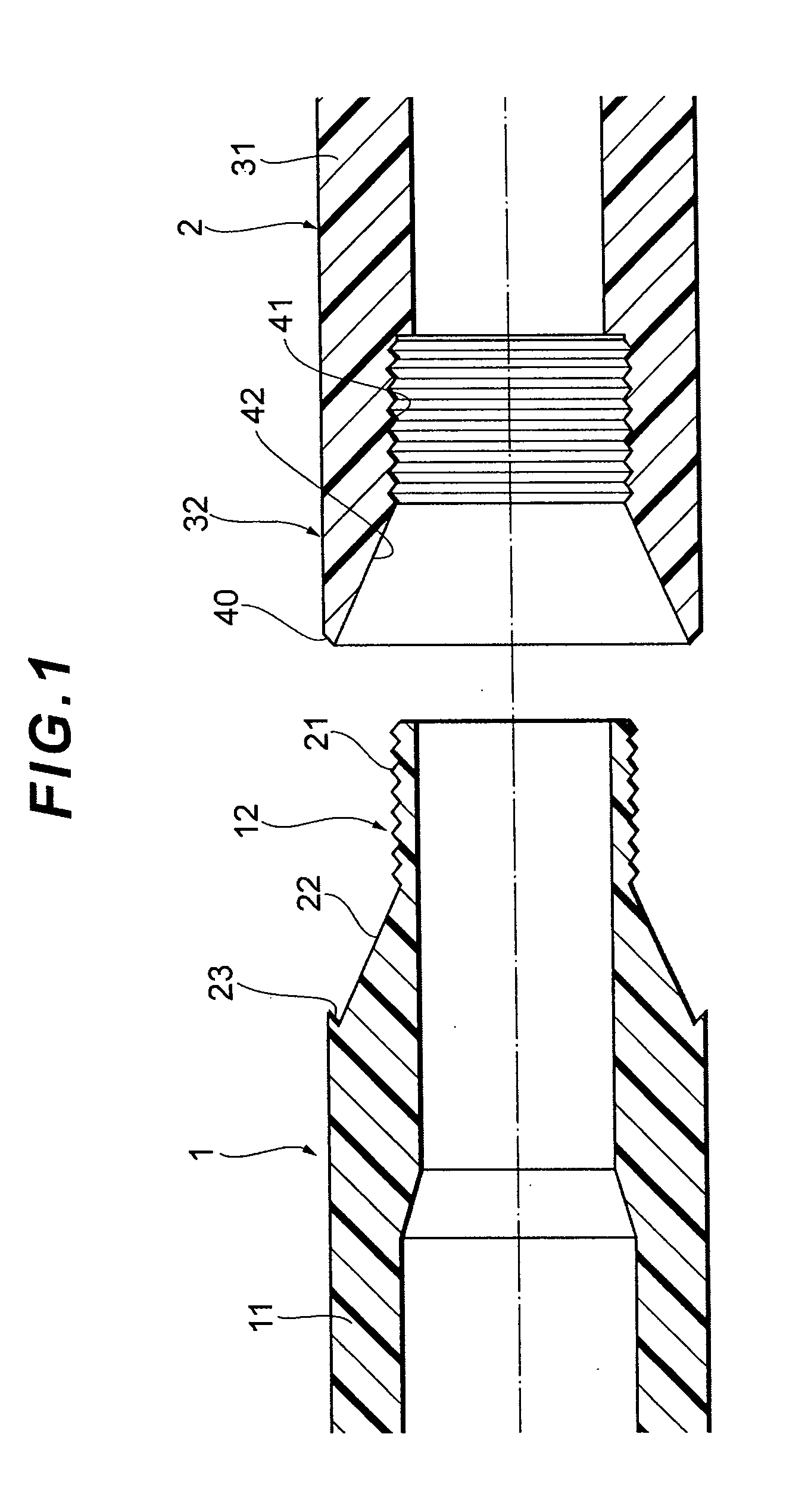
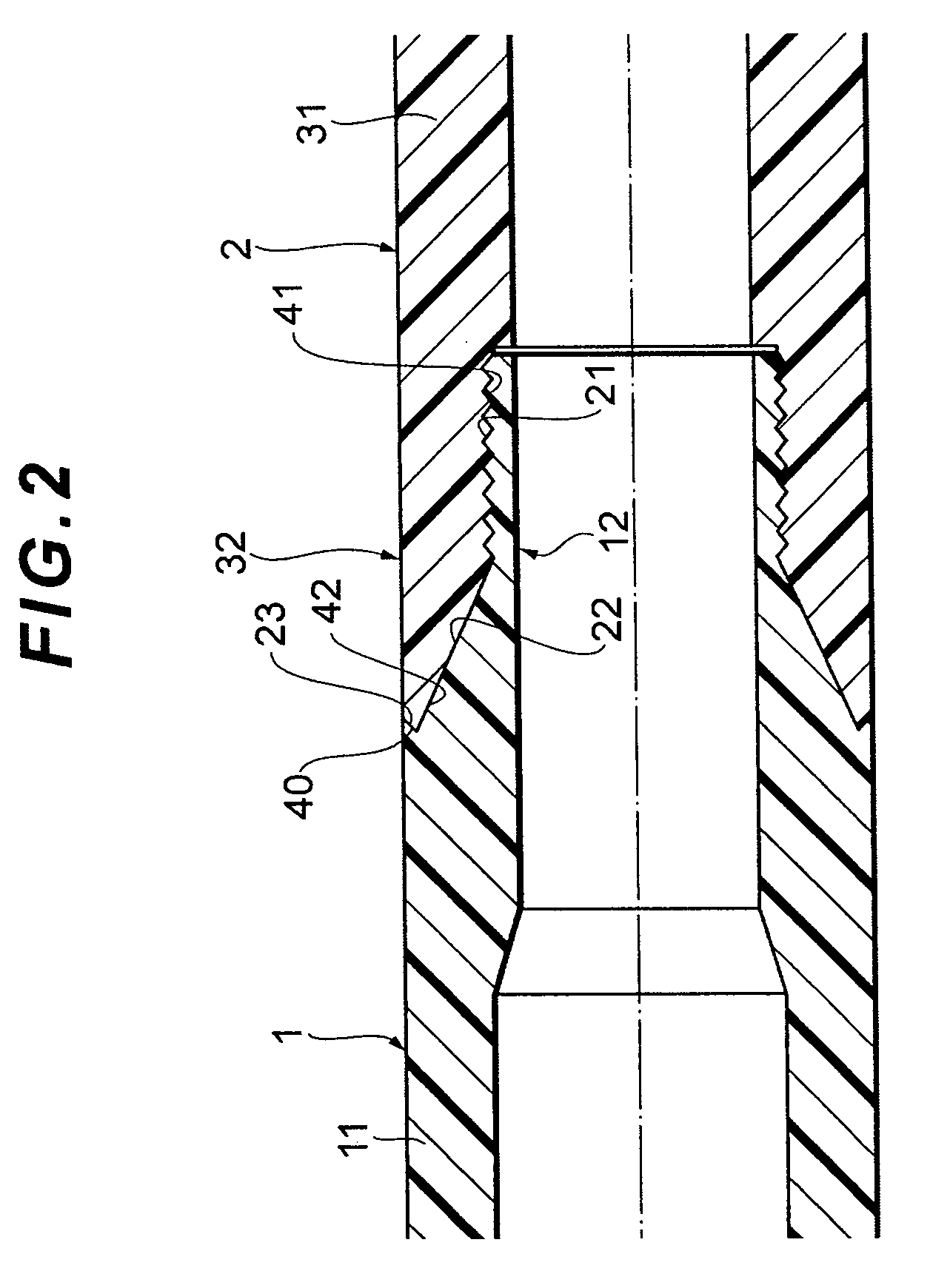
[0070]As shown in FIGS. 1 and 2, a pipe material 1 (a first resin member) made of a laser absorbing resin is bonded to a pipe material 2 (a second resin member) made of a laser transmitting resin to form one pipe-like molded resin material. Both of the pipe materials 1, 2 have a cylindrical shape as a whole, have an equal outer diameter, and are bonded to each other while the materials are aligned with each other in an axial direction.

[0071]The laser absorbing pipe material 1 has a trunk portion 11 which extends along a predetermined length in an axial direction of the material, and a substantially cylindrical bonding end portion 12 (a first end portion) formed on the side of one opened end of the trunk portion 11. An outer peripheral surface of the bonding end portion 12 has an external thread 21 formed on a tip-end side and having a diameter smaller than an outer diameter of the trunk portion 11, a bonding surface 22 sloped at a predetermined angle from a base end side of the exte...

second embodiment

[0091]Next, mainly different respects of a bonded structure of two members and a bonding method of the members according to a second embodiment will be described with reference to FIG. 4. The embodiment is different from the first embodiment in that an external thread 21 and an internal thread 41 are made of a metal material. It is to be noted that a part common to the first embodiment is denoted with the same reference numerals as those of the first embodiment, and detailed description thereof is omitted.

[0092]A metal sleeve 70 having the external thread 21 on an outer peripheral surface thereof is provided on an outer periphery of a small-diameter cylindrical portion 72 formed on a tip end of a bonding end portion 12. The metal sleeve 70 is formed on a pipe material 1 by insertion molding. It is to be noted that the metal sleeve may be fitted into the outer periphery of the small-diameter cylindrical portion 72, or bonded with adhesive in this fitted state.

[0093]A metal sleeve 80 ...

third embodiment

[0096]Next, a gas container and a bonding method of the container according to a third embodiment will be described with reference to FIGS. 5 and 6. In the present embodiment, a bonded structure of two members of the first embodiment is applied to a resin liner of the gas container, and end portions of a liner constituting member constituting the resin liner are bonded to each other. First, a structure of the gas container will hereinafter be described. Subsequently, a manufacturing method of the gas container will briefly be described.

[0097]As shown in FIG. 5, a gas container 101 includes a container main body 102 having a hermetically sealed cylindrical shape as a whole; and mouthpieces 103, 103 attached to opposite end portions of the container main body 102 in a longitudinal direction. An inner part of the container main body 102 is a storage space 105 to store various types of gases. The gas container 101 may be filled with gas having a normal pressure, or gas having a raised p...


PUM

PropertyMeasurementUnit
pressureaaaaaaaaaa
pressureaaaaaaaaaa
pressureaaaaaaaaaa

Abstract

An object is to provide a bonded structure of two members, a bonding method of two members in which end portions of a pair of resin members can appropriately be bonded to each other by laser welding while easily suppressing a positional deviation between the end portions of the resin members, a gas container and a manufacturing method of the gas container. In the bonded structure of two members, an external thread provided at a substantially cylindrical end portion of a resin member is screwed into an internal thread provided at a substantially cylindrical end portion of a resin member and irradiated with laser to bond the end portions of the resin members to each other by the laser welding. In the gas container, this bonded structure is applied to a resin liner of the gas container, and liner constituting members are screwed and bonded by the laser welding.

Description

TECHNICAL FIELD [0001]The present invention relates to a bonded structure of two members in which substantially cylindrical end portions of a pair of resin members are bonded to each other, and a method of the bonded structure. The present invention also relates to a gas container including a resin liner constituted by bonding a plurality of liner constituting members, more particularly to a gas container in which end portions of the liner constituting members to be bonded have a cylindrical shape. The present invention further relates to a manufacturing method of the gas container.BACKGROUND ART [0002]Heretofore, from viewpoints of lightening and the like, pipe-like materials constituting a piping line and the like and an inner shell (a liner) of a gas container are made of a resin to form a molded resin material. Such type of molded resin material is constituted by bonding divided molded materials, which are divided and molded beforehand, to one another in many cases. In this case...

Claims


Application Information

Patent Timeline
Patent Type & Authority Applications(United States)
IPC IPC(8): B32B1/02B29C65/16B32B1/08
CPCB29C65/1635Y10T428/1352B29C65/1683B29C65/561B29C65/58B29C65/72B29C66/54B29C66/65B29C66/652B29C66/7332B29K2023/06B29K2023/12B29K2077/00B29K2101/12B29K2309/08B29K2995/0026B29K2995/0027B29K2995/0029B29L2022/00B29L2031/7156F16L47/02F17C1/16B29C65/168B29C66/5221B29C66/543Y02E60/321F17C2205/0397F17C2201/0109F17C2203/0604F17C2203/0619F17C2203/0663F17C2205/0305F17C2209/221F17C2209/232F17C2209/234F17C2221/012F17C2221/033F17C2223/0123F17C2223/036F17C2260/011F17C2270/05B29C65/1654B29C65/1677B29C65/00B29C66/1162B29C66/71B29C66/712B29C66/7212B29C66/73921Y02E60/32B29K2023/04B29K2023/10
Inventor AMANO, MASAAKI
Owner TOYOTA JIDOSHA KK
Why Eureka
Try Eureka