Light-emitting device, method for manufacturing same, and molded part
a technology of light-emitting devices and molding parts, which is applied in the direction of discharge tubes luminescnet screens, other domestic articles, transportation and packaging, etc., can solve the problems of poor adhesion of resins to leads and sealing members, poor heat resistance and light resistance of prior art thermoplastic resins used as moldings in surface mount light-emitting devices, and lack of long-term reliability of sealing members using silicone resins. , to achieve the effect of improving heat resistance and light resistan
Active Publication Date: 2008-08-07
NICHIA CORP
View PDF14 Cites 51 Cited by
- Summary
- Abstract
- Description
- Claims
- Application Information
AI Technical Summary
Benefits of technology
[0022]With the method described above, a light-emitting device comprising a molded part comprising a thermosetting epoxy resin composition in the cured state is readily manufactured.
[0023]In a further aspect, the invention provides a molded part for use in a light-emitting device, comprising a thermosetting epoxy resin composition in the cured state. The epoxy resin composition comprises (A) a reaction product obtained through reaction of a triazine derived epoxy resin with an acid anhydride in an epoxy group equivalent to acid anhydride group equivalent ratio from 0.6 to 2.0, (B) an internal parting agent, (C) a reflective agent, (D) an inorganic filler, and (E) a curing catalyst as essential components. The internal parting agent (B) comprises a
Problems solved by technology
However, prior art thermoplastic resins used as moldings in surface mount light-emitting devices are less resistant to light due to the inclusion of an aromatic component within the molecule although they are resistant to heat.
Also, since hydroxyl groups or other groups for improving adhesion are absent at molecular ends, the resins exhibit poor adhesion to leads and sealing members.
In particular, sealing members using silicone resins lack long-term reliability since they show a drastic
Method used
View moreImage
Smart ImageViewing Examples

Examples
example
[0077]Examples and Comparative Examples are given below for further illustrating the invention although the invention is not limited to these Examples.
Login to view more PUM
| Property | Measurement | Unit |
|---|---|---|
| Temperature | aaaaa | aaaaa |
| Temperature | aaaaa | aaaaa |
| Percent by mass | aaaaa | aaaaa |
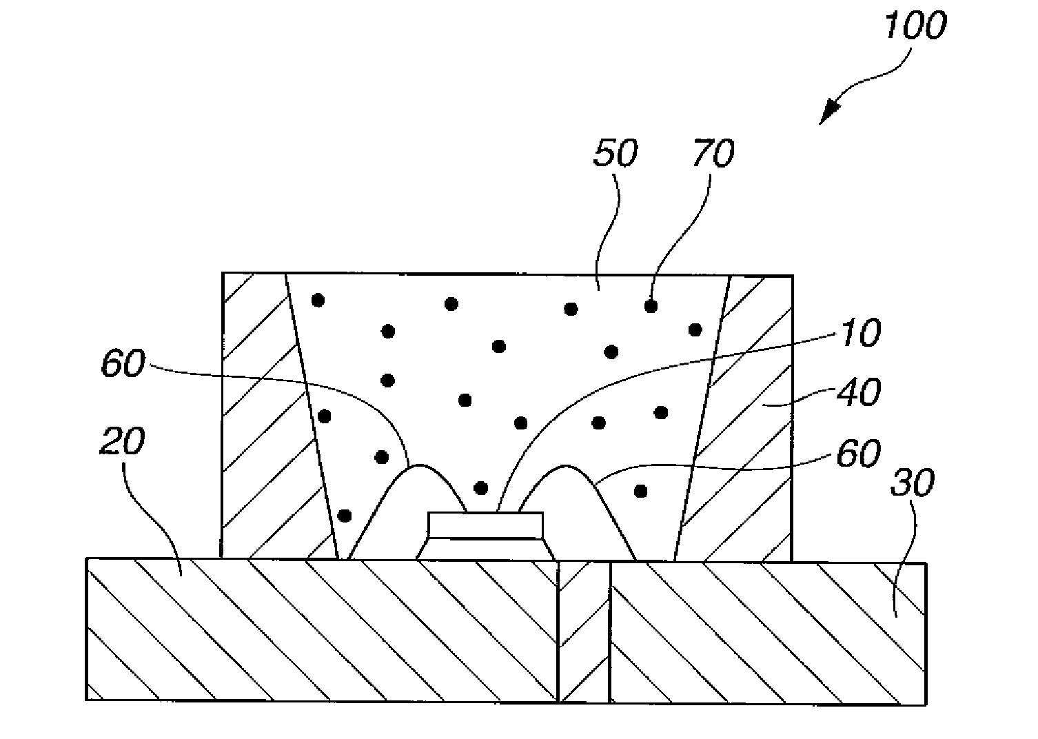
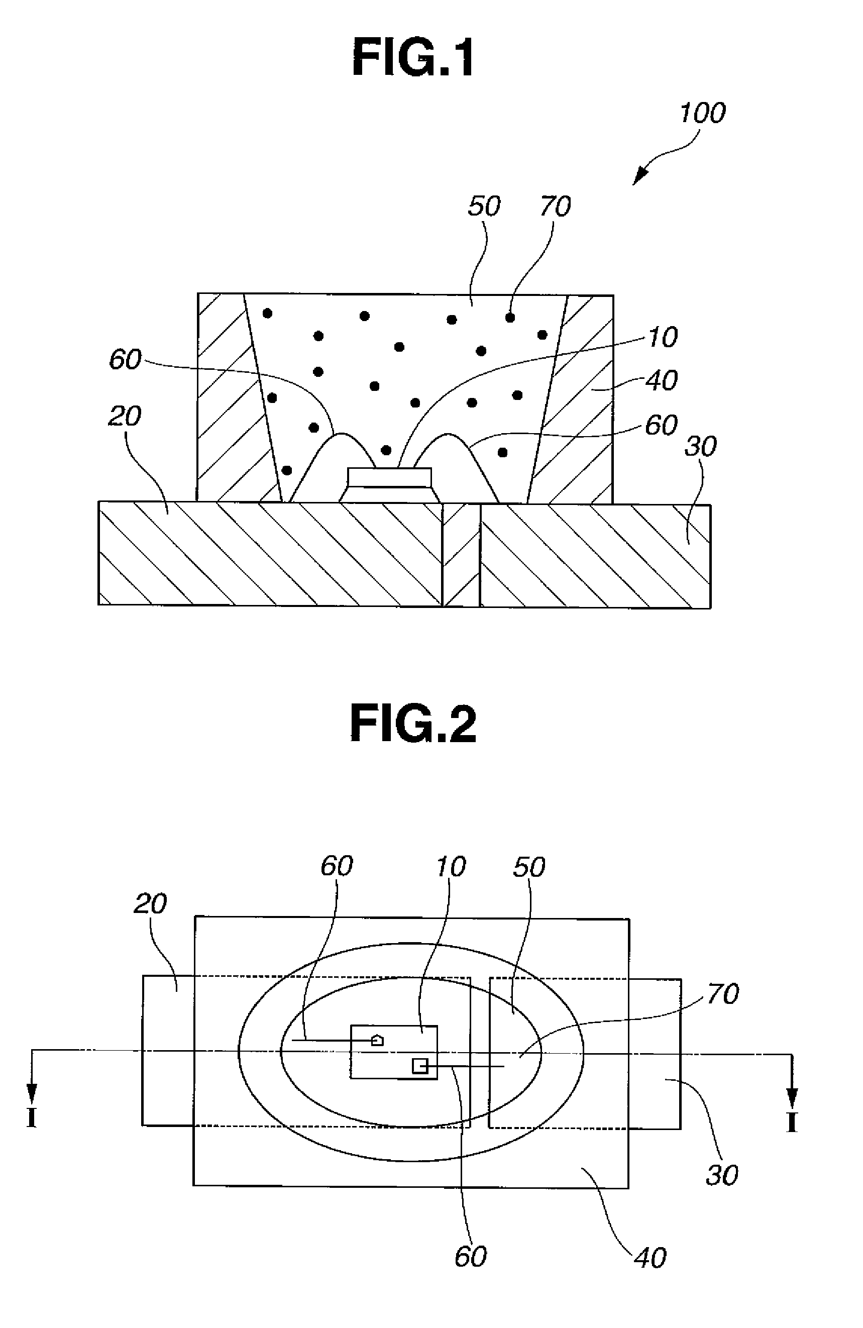
Abstract
A light-emitting device includes a light-emitting element on a molded part. The molded part is formed by molding and curing a thermosetting epoxy resin composition comprising (A) the reaction product of a triazine derived epoxy resin with an acid anhydride, (B) an internal parting agent having m.p. 50-90° C., (C) a reflective agent, (D) an inorganic filler, and (E) a curing catalyst.
Description
CROSS-REFERENCE TO RELATED APPLICATION[0001]This non-provisional application claims priority under 35 U.S.C. §119(a) on Patent Application No. 2007-026693 filed in Japan on Feb. 6, 2007, the entire contents of which are hereby incorporated by reference.TECHNICAL FIELD[0002]This invention relates to a light-emitting device for use as luminaires, displays, mobile phone backlights, moving picture illuminating auxiliary light sources, and other general commercial light sources, a method for manufacturing the same, and a molded part.BACKGROUND ART[0003]Surface mount light-emitting devices using light-emitting elements feature a small size, a good power efficiency, and light emission of brilliant color. The light-emitting elements eliminate the risk of lamp failures since they are semiconductor elements. They are also characterized by improved initial drive performance and resistance to vibration and repeated turn-on and off. Because of these improved properties, light-emitting devices us...
Claims
Login to view more Application Information
Patent Timeline
 IPC IPC(8): H01J1/63B29C45/02H01L33/32H01L33/56H01L33/60
CPCB29C45/02B29D11/0074B29K2063/00B29C45/2806H01L2924/181H01L2224/48247H01L2224/48257H01L2224/73265H01L33/60H01L33/486H01L2933/0058Y10T428/31511H01L2924/00012
Inventor HAYASHI, MASAKITAMAKI, HIROTOKURAMOTO, MASAFUMIMIKI, TOMOHIDESANO, TAKAYUKIKISHIMOTO, TOMOHISA
Owner NICHIA CORP
- R&D Engineer
- R&D Manager
- IP Professional
Why Eureka
- Industry Leading Data Capabilities
- Powerful AI technology
- Patent DNA Extraction
Try Eureka
Browse by: Latest US Patents, China's latest patents, Technical Efficacy Thesaurus, Application Domain, Technology Topic.
© 2024 PatSnap. All rights reserved.Legal|Privacy policy|Modern Slavery Act Transparency Statement|Sitemap