
Engine control apparatus using signal with level changing with engine operation

a technology of engine control and signal, which is applied in the direction of electric control, speed sensing governors, instruments, etc., can solve the problems of reducing the control accuracy of the engine control unit, and achieve the effect of reducing the engine control accuracy

Active Publication Date: 2008-08-07
DENSO CORP
View PDF13 Cites 12 Cited by
  • Summary
  • Abstract
  • Description
  • Claims
  • Application Information

AI Technical Summary

Benefits of technology

[0017]In the engine control unit disclosed in the JP Patent Application Publication No. 2001-200747, when a time interval between temporally adjacent predetermined-directed level changes in the irregular region of the crank signal is measured, even before the measured time interval is corrected, an angle clock is generated based on the measured time interval before correction.
[0018]For this reason, even a period up to the correction, the angle clock generated based on the measured time interval before the correction may cause the accuracy of the angle clock, contributing to the reduction in the engine control accuracy for the engine control unit.
[0019]In view of the background, an object of at least one aspect of the resent invention is to provide engine control apparatuses, which are capable of generating an operation clock having an accuracy higher than that of operation clocks to be generated by conventional engine control apparatuses.
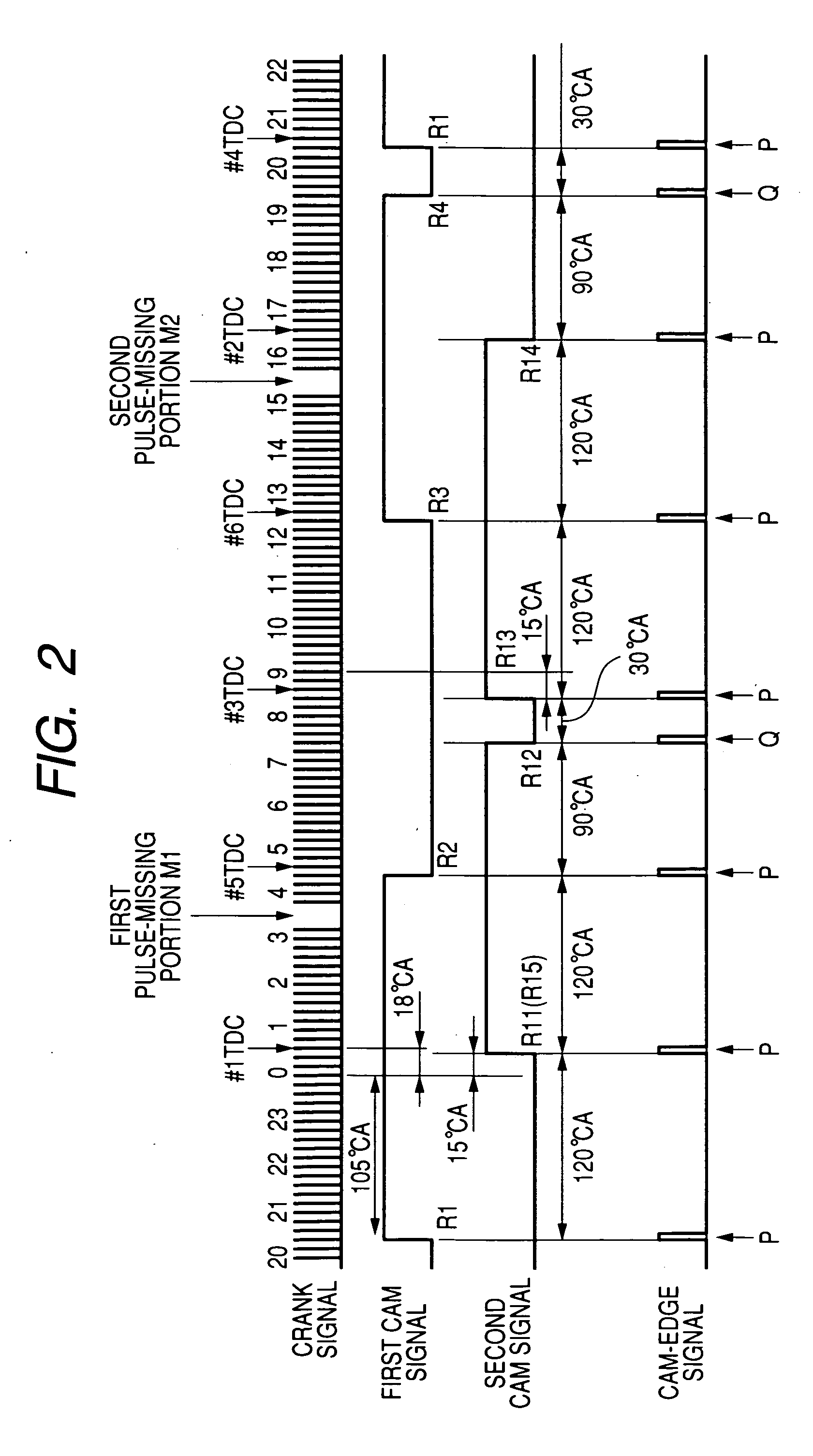
[0020]According to an aspect of the present invention, there is provided an apparatus for controlling an engine. The apparatus includes an interval measuring unit configured to receive an input signal input thereto and composed of a regular region and an irregular region repetitively appearing in time. The input signal has a level that regularly changes in time in a predetermined direction in the regular region thereof every amount of regular operation of the engine. The level of the input signal irregularly changes in time in the predetermined direction in the irregular region thereof with an amount of irregular operation of the engine. The interval measuring unit is configured to sequentially measure an interval between appearance of a predetermined-directed level change in the input signal and that of a temporally next predetermined-directed level change therein. The apparatus includes a multiplication clock generating unit configured to sequentially use one of the measured intervals as a reference interval and to divide, by a multiplication number, the reference interval so as to generate a multiplication clock, the multiplication clock including a train of clock pulses whose clock cycle corresponds to a division of the reference interval by the multiplication number. The apparatus includes an engine control unit configured to control the engine in synchronization with the multiplication clock generated by the multiplication clock generating unit. The apparatus includes an irregular-region start detector configured to detect that a predetermined-directed level change in the input signal is synchronized with a start of appearance of the irregular region thereof. The apparatus includes an irregular-region end detector configured to detect that a predetermined-directed level change in the input signal is synchronized with an end of the irregular region thereof. The apparatus includes a fixing unit configured to fix the reference interval to a predetermined value when it is detected that the predetermined-directed level change in the input signal is syn

Problems solved by technology

For this reason, even a period up to the correction, the angle clock generated based on the measured time interval before the correction may cause the accuracy of the angle clock, contributing to the reduction in the engine control accuracy for the engine control unit.

Method used


Image

  • Engine control apparatus using signal with level changing with engine operation
  • Engine control apparatus using signal with level changing with engine operation
  • Engine control apparatus using signal with level changing with engine operation

Examples


Embodiment Construction

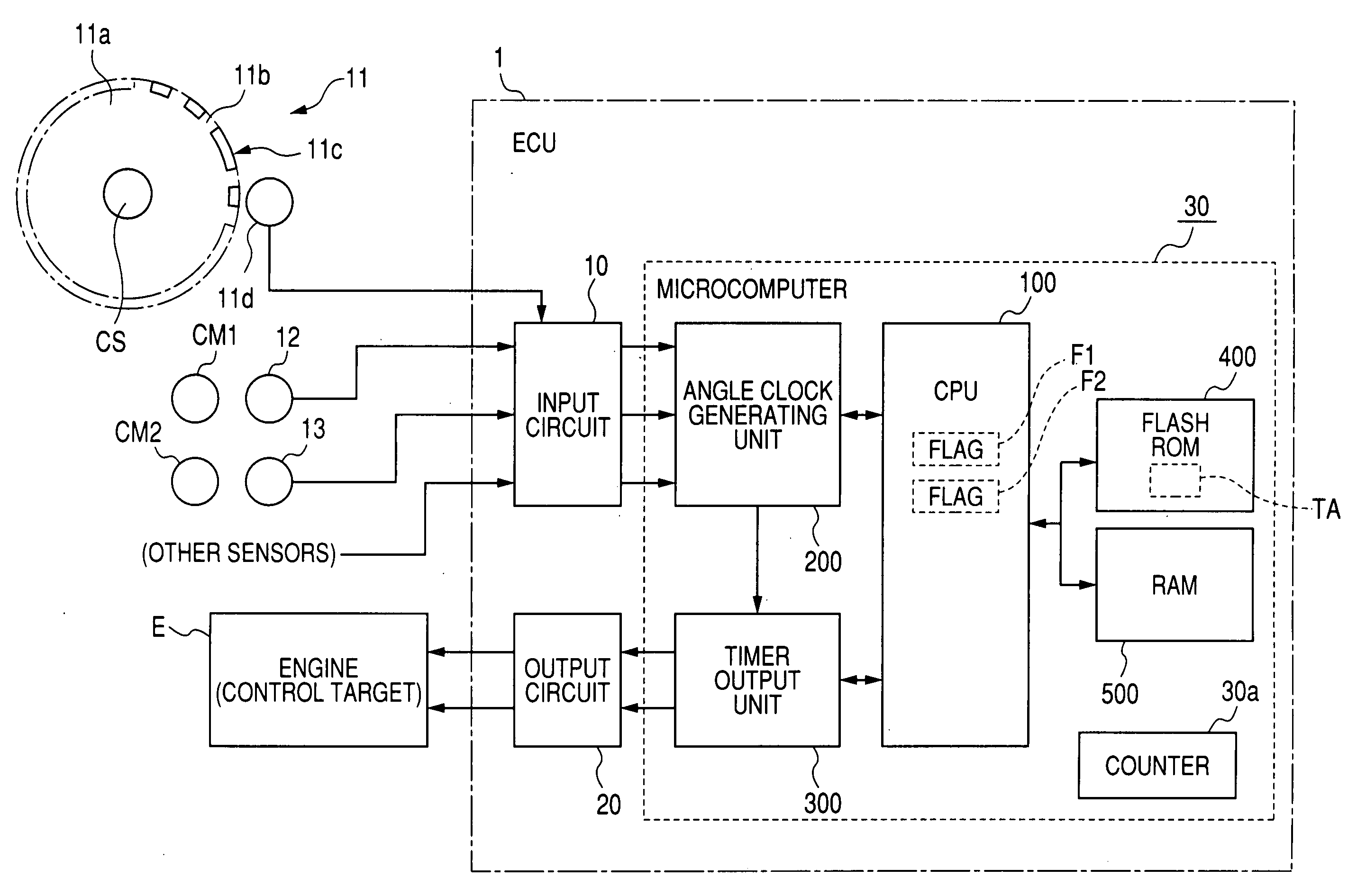
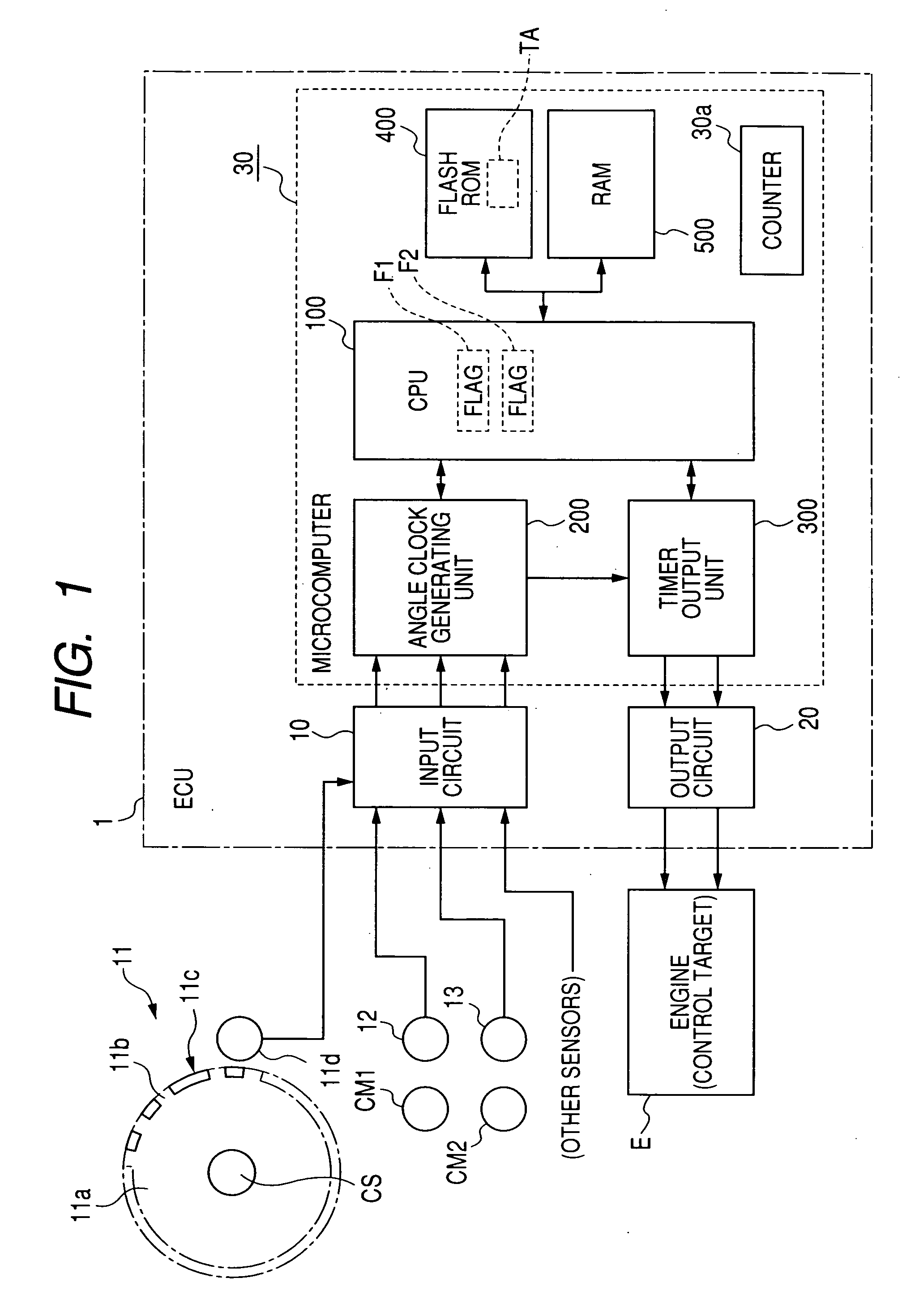
[0037]An embodiment of the present invention will be described hereinafter with reference to the accompanying drawings. In the embodiment, the invention is applied to an electronic control unit (ECU) 1, and the ECU 1 serves as an engine control unit operative to control a four-cycle internal combustion engine E installed in a vehicle and having, for example, the first (#1) to sixth (#6) cylinders.

[0038]FIG. 1 is a block diagram illustrating an example of the structure of the ECU 1, which is installed in advance in the vehicle according to the embodiment of the present invention.

[0039]Referring to FIG. 1, the ECU 1 according to the embodiment is provided with an input circuit 10, an output circuit 20, and a microcomputer 30. The input and output circuits 10 and 20 are electrically connected to the microcomputer 30.

[0040]The input circuit 10 is electrically connected to a crankshaft sensor 11, a first camshaft sensor 12, a second camshaft sensor 13, and other sensors.

[0041]As illustra...


PUM


Abstract

In an apparatus for controlling an engine, an irregular-region start detector detects that a predetermined-directed level change in an input signal is synchronized with a start of appearance of an irregular region thereof. An irregular-region end detector detects that a predetermined-directed level change in the input signal is synchronized with an end of the irregular region thereof. A fixing unit fixes a reference interval to a predetermined value when it is detected that the predetermined-directed level change in the input signal is synchronized with the start of appearance of the irregular region thereof. A resetting unit resets the reference interval from the predetermined-value to one of the measured intervals when it is detected that the predetermined-directed level change in the input signal is synchronized with the end of the irregular region thereof.

Description

CROSS REFERENCE TO RELATED APPLICATION[0001]This application is based on Japanese Patent Application 2007-022808 filed on Feb. 1, 2007 and claims the benefit of priority therefrom, so that the descriptions of which are all incorporated herein by reference.BACKGROUND OF THE INVENTION[0002]1. Field of the Invention[0003]The present invention relates to apparatuses for controlling an engine based on a signal having a level changing with operations of the engine.[0004]2. Description of the Related Art[0005]Engine control units for vehicles use a crank signal whose signal level varies in a predetermined same direction at regular rotation angles (regular crank angles) of an engine crankshaft. When the crank signal is measured by a crankshaft sensor connected to an engine control unit, the measured crank signal is input to the engine control unit.[0006]Based on the input crank signal, the engine control unit works to identify a rotational position (crank position) of the crankshaft; this r...

Claims


Application Information

Patent Timeline
IPC IPC(8): F02D45/00
CPCF02D41/009F02D2250/14F02D41/2403
Inventor KONDO, HARUHIKO
Owner DENSO CORP
Learn More