Refrigerator

a technology of refrigerators and refrigerators, which is applied in the field of refrigerators, can solve the problems of low relative humidity in the refrigerating chamber, inability to finely set temperature, and inability to improve the efficiency of the freezing cycle, so as to achieve the effect of reducing the flow ratio of refrigerators to one evaporator, reducing pressure loss, and improving cooling efficiency

Inactive Publication Date: 2008-08-14
TOSHIBA HA PROD +2
View PDF6 Cites 55 Cited by
  • Summary
  • Abstract
  • Description
  • Claims
  • Application Information

AI Technical Summary

Benefits of technology

[0070]Therefore, according to the invention stated in Claim 22, the next return value is set according to the too high or low refrigerant flow rate, thus when the refrigerant flow rate to one evaporator is next controlled to the return value, the refrigerant flow rate by the return value can be controlled appropriately.
[0071]According to the invention stated in Claim 23, in the circumstance that the refrigerant flow rate to one evaporator is limited and adjusted, when the number of revolutions of the compressor is large, the pressure loss at the limiting section of the refrigerant is large, and the cooling efficiency is lowered, though when the number of revolutions of the compressor is large, the upper limit value is provided for the refrigerator flow ratio to one evaporator, and thus the refrigerator flow ratio to one evaporator is increased and the pressure loss can be prevented.
[0072]When the air temperature in the installation place of the refrigerator is low, the load of the freezing cycle is reduced, and the control for the refrigerant flow ratio on the basis of the superheat amount of one evaporator can be executed appropriately, so that if the upper limit value is made higher when the air temperature is low, the refrigerant amount to one evaporator is too large, and the superheat amount overshoots excessively, though according to the invention stated in Claim 24, when the air temperature is low, the upper limit value is not changed, thus the refrigerant flow rate into one evaporator can be prevented from excessive.

Problems solved by technology

In the refrigerator aforementioned, in the simultaneous cooling mode for simultaneously cooling the refrigerating chamber and freezing chamber, the evaporation temperature of the R evaporator and the evaporation temperature of the F evaporator are the same, thus a problem arises that the efficiency of the freezing cycle cannot be improved.
Further, the absolute value of the evaporation temperature of the R evaporator is low, so that a problem arises that the relative humidity in the refrigerating chamber is low.
Furthermore, the on-off valve is switched when it is necessary to cool each of the freezing chamber and the refrigerating chamber, so that a loss is caused in the on-off valve and the temperature of either of the chambers rises during the waiting time in the alternate cooling, and thus a problem arises that the temperature cannot be set finely and a higher constant temperature performance cannot be obtained.
This refrigerator can simultaneously cool the two sections of the freezing section and the refrigerating section, though a suction pressure of the compressor is restricted by a pressure of the freezing evaporator having a low evaporation temperature, so that it is difficult to enhance the efficiency of the freezing cycle.
In such a constitution, the refrigerant is distributed to the freezing evaporator and refrigerating evaporator by the flow rate resistance of capillary tubes connecting the condenser and evaporators, and it is difficult to control the refrigerant flow rate flowing through the capillary tubes depending on the condition of each evaporator, so that the cooling capacity of each evaporator cannot be controlled.
However, an appropriate refrigerant amount to the evaporators is always varied according to the operating condition of the refrigerator, so that even if the refrigerant flow rate to one evaporator is limited and adjusted, there is no method available for correctly judging whether the refrigerant flow rate to one evaporator is appropriate or not, and a problem is left unsolved that the flow rate adjustment cannot be executed appropriately.
Therefore, it is considered to install temperature sensors for detecting an entrance temperature and an exit temperature of one evaporator, to obtain a superheat amount (the difference between the exit temperature and the entrance temperature) of one evaporator from the temperature sensors, and to control appropriately the superheat amount, though when the accuracy of the temperature sensors is low, the control on the basis of such a superheat amount is difficult.
Further, as a result of limiting and adjusting the refrigerant flow rate to one evaporator, when the supply of the refrigerant to one evaporator is stopped or the refrigerant flow rate is limited to a minimum refrigerant flow ratio, even if the refrigerant is next supplied to one evaporator, a delay is caused under the ordinary control until a sufficient refrigerant is supplied to one evaporator, and there is a fear that obstacles may be caused in limiting and adjusting one evaporator.

Method used


Image

  • Refrigerator
  • Refrigerator
  • Refrigerator

Examples


Embodiment Construction

[0108]Referring now to the drawings, wherein like reference numerals designate identical or corresponding parts throughout the several views, the embodiments of this invention will be described below.

[0109]Firstly, an embodiment of the present invention will be explained with reference to FIGS. 1 to 6.

(1) Structure of a Refrigerator 1A

[0110]Firstly, the structure of refrigerator 1A will be explained by referring to FIG. 3.

[0111]Inside refrigerator 1A, starting from the upper stage, a refrigerating chamber 2A, a vegetable chamber 3A, an ice making chamber 4A, and a freezing chamber 5A are installed.

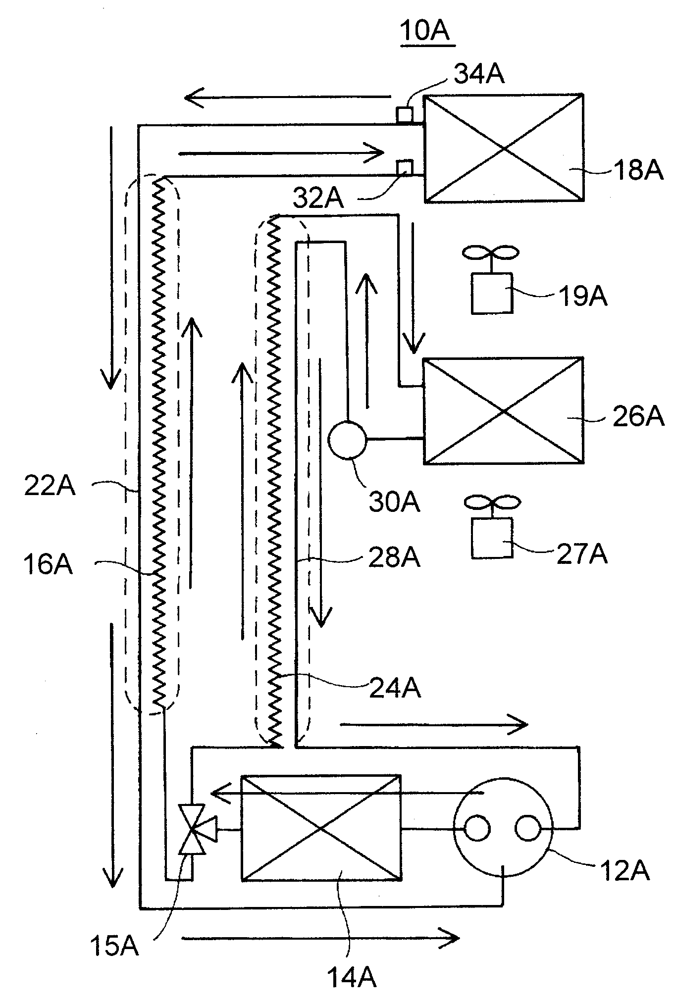
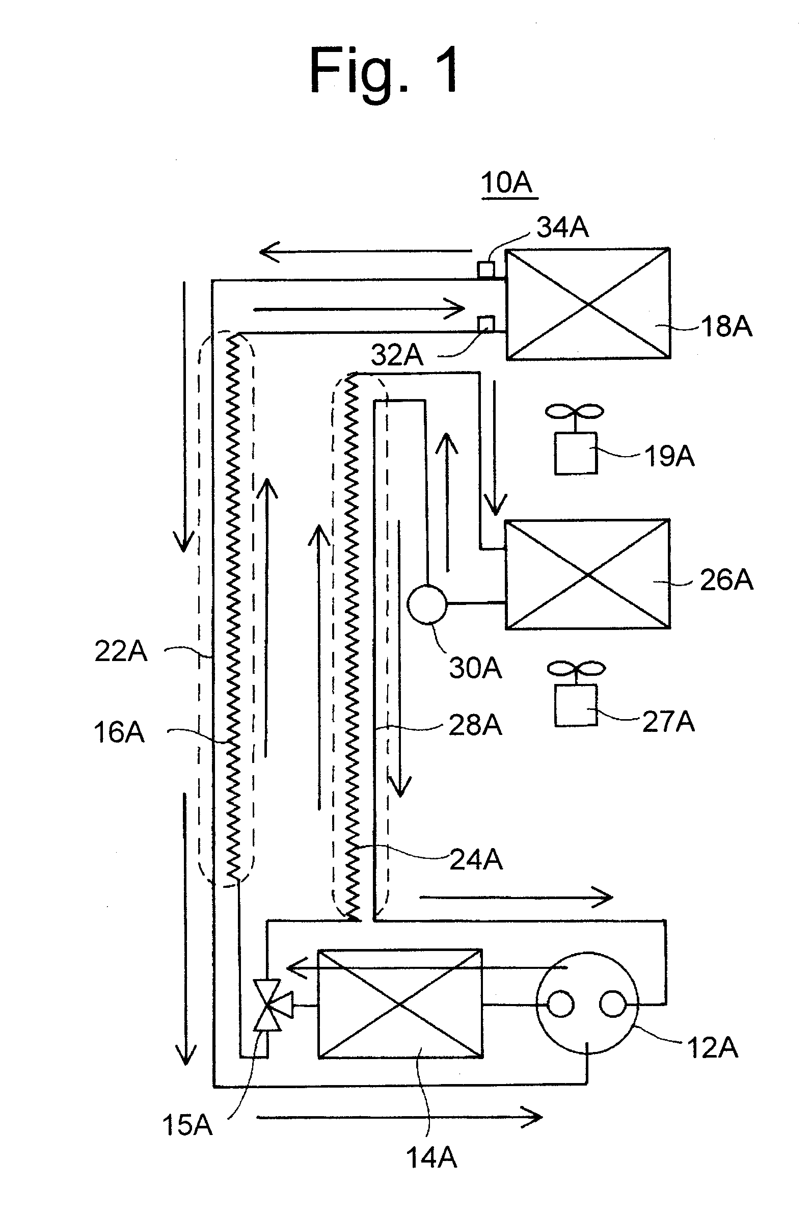
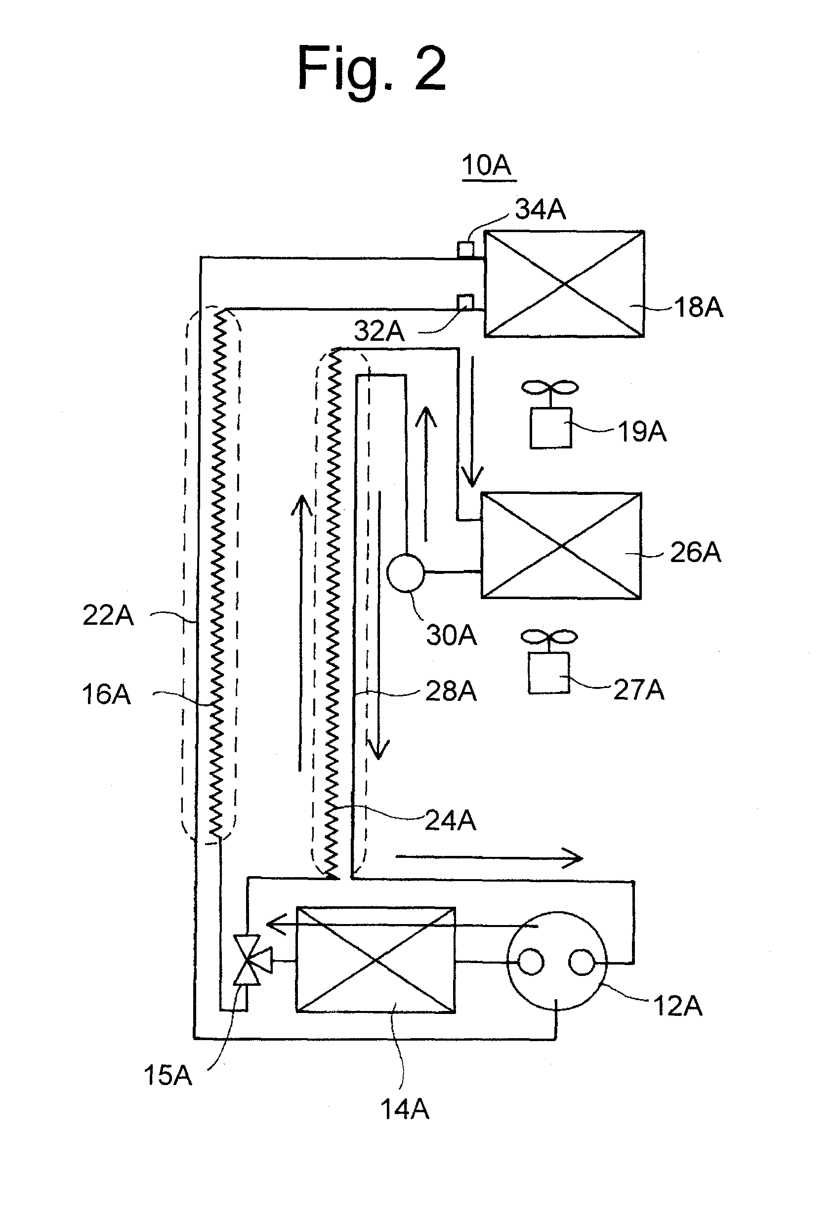
[0112]In a machine chamber 6A on the back of freezing chamber 5A, a two-stage compressor (hereinafter, referred to as just a compressor) 12A of a capacity variable type is installed.

[0113]On the back of ice making chamber 4A, an evaporator (hereinafter, referred to as an F evaporator) 26A for a freezing chamber for cooling ice making chamber 4A and freezing chamber 5A is installed.

[0114]Fu...


PUM


Abstract

A high-pressure side discharge port of a two-stage compressor (12A) and a condenser (14A) are connected, condenser (14A) and a PMV (15A) are connected, a refrigerating side exit of PMV (15A) is connected to a medium pressure side suction port of two-stage compressor (12A) via an R capillary tube (16A) and an F evaporator (18A), connected to an F evaporator (26A) via an F capillary tube (24A), F evaporator (26A) is connected to a low-pressure side suction port of two-stage compressor (12A) via a low-pressure suction pipe (28A), PMV (15A) can switch a simultaneous cooling mode and a freezing mode, and in the simultaneous cooling mode, a refrigerant flow rate toward R evaporator (18A) is adjusted by PMV (15A), and thereby a temperature difference control is performed so as to make a difference between an entrance temperature and an exit temperature of R evaporator (18A) equal to a preset temperature difference (for example, 4° C.).
A controller (22), on the basis of the detection condition of a temperature sensor (23) for a freezing chamber and a temperature sensor (24) for a refrigerating chamber, controls a freezing cycle device (10). Here, controller (22) controls an opening of a regulating valve (12) so as to make a superheat amount which is a difference between an exit temperature and an entrance temperature of a refrigerating evaporator (5) equal to a target superheat amount, and thereby adjusts a refrigerant flow rate to refrigerating evaporator (5) in a limited state.
In this case, when a power is turned on, the entrance temperature and the exit temperature of refrigerating evaporator (5) are the same, so that controller (22), when the power is turned on, calibrates detected temperatures of an entrance temperature sensor (27) and an exit temperature sensor (26) so as to coincide with each other, and thereby can execute surely the subsequent limiting adjustment of regulating valve (12) on the basis of the superheat amount.
Further, in this case, when a refrigerant supply to refrigerating evaporator (5) is stopped and the temperature of refrigerating evaporator (5) rises suddenly, controller 22 increases an opening of a valve opening (42) to refrigerating evaporator (5) of regulating valve (12) to a predetermined return value, so that the refrigerant supply amount to refrigerating evaporator (5) is increased at a stretch, and thus the refrigerating evaporator can be cooled quickly.
A refrigerator having a two-stage compressor (12A) for cooling efficiently both a refrigerating chamber (2A) and a freezing chamber (5A) will be provided.
When limiting and adjusting a refrigerant flow rate to one evaporator according to an opening of a valve body so as to make a superheat amount of one evaporator appropriate on the basis of the superheat amount which is a difference between an exit temperature and an entrance temperature of one evaporator, a refrigerator for detecting accurately the entrance temperature and the exit temperature of one evaporator will be provided.
When limiting and adjusting a refrigerant flow rate to one evaporator according to an opening of a valve body, a refrigerator for causing no delay in a refrigerant supply to one evaporator will be provided.

Description

TECHNICAL FIELD[0001]The present invention relates to a refrigerator of a type of supplying a refrigerant to an evaporator for a freezing chamber and an evaporator for a refrigerating chamber.BACKGROUND ART[0002]Conventionally, as a refrigerator having a freezing cycle of sending a refrigerant to two evaporators using a two-stage compressor, the following is proposed.[0003]Namely, a refrigerator with an on-off valve installed at an exit of a condenser is proposed, which by switching the on-off valve, executes a simultaneous cooling mode for supplying a refrigerant sequentially to a refrigerating evaporator (hereinafter referred to as an R evaporator) and a freezing evaporator (hereinafter referred to as an F evaporator), and thereby for simultaneously cooling the R evaporator and the F evaporator, or executes a cooling mode for supplying a refrigerant only to a freezing evaporator (hereinafter referred to as an F evaporator) via a bypass tube from the on-off valve (for example, refe...

Claims


Application Information

Patent Timeline
Patent Type & Authority Applications(United States)
IPC IPC(8): F25B41/00F25B41/04F25B43/00F25B5/02F25B1/00F25B1/10F25D11/02
CPCF25B1/10F25B5/02F25B2400/052F25B2400/054F25B2600/112Y02B40/32F25D11/022F25D29/00F25D2400/04Y02B30/743F25B2600/2511F25B2500/31Y02B30/70Y02B40/00F25B1/00F25D19/00
Inventor YOSHIOKA, TAKAHIROHAYASHI, HIDETAKETEMMYO, MINORU
Owner TOSHIBA HA PROD
Why Eureka
Try Eureka