
Electrode Tip Holder, Welding Method, and Electrode Tip Adjusting Device

a technology of electrode tip and electrode tip, which is applied in the direction of electrode features, welding apparatus, manufacturing tools, etc., can solve the problems of inability to replace the electrode tip with the tip replacement apparatus, inability to replace the electrode tip, and inability to consume the electrode tip, so as to increase the overall welding efficiency, easy and fast installation of the electrode tip, and move appropriately with ease

Inactive Publication Date: 2008-08-14
HONDA MOTOR CO LTD
View PDF1 Cites 18 Cited by
  • Summary
  • Abstract
  • Description
  • Claims
  • Application Information

AI Technical Summary

Benefits of technology

[0010]It is an object of the present invention to provide an electrode tip holder and a welding method which allow an electrode tip to be replaced at a prolonged time interval or within a shortened period of time for increasing the efficiency of an overall welding process.
[0011]Another object of the present invention is to provide an electrode tip adjusting apparatus which allows an electrode tip to be replaced at a prolonged time interval or within a shortened period of time for increasing the efficiency of an overall welding process.

Problems solved by technology

Electrode tips mounted on electrode tip holders are inevitably consumed due to electric discharges, etc. as they are used to weld workpieces.
Since the manual replacement tends to be inefficient as the time required for replacement varies from operator to operator, it has been desired to replace the worn electrode tip automatically within a shortened period of time.
Therefore, the tip replacing apparatus is unable to replace electrode tips having other shapes than the disclosed shape.
If the electrode tip is pushed in under too weak forces, then the electrode tip may accidentally drop off the shank in the welding process.
If the electrode tip is supplied with the coolant as disclosed in Japanese Patent No. 3347436, then since a liquid-tight seal needs to be provided by the abutting engagement of tapered surfaces, it is necessary to machine the tapered surfaces to a nicety, resulting in an increased cost.
Practically, an actual match of tapered surfaces may be necessary to provide a suitable liquid-tight structure because of lack of accuracy for individual tapered surfaces.
When the electrode tip is replaced, the shank is exposed, tending to make its tapered surface susceptible to damage.
If the shank is damaged, then it also has to be replaced.
Because the electrode tip needs to have a shank connector and a coolant passage hole, its portion to be effectively used as an electrode is limited to a small area on its distal end.
Accordingly, the electrode tip needs to be frequently replaced as its electrode wears quickly.
In addition, much of the material of the electrode tip is wasted because the shank connector is not used as an electrode.
Therefore, when the electrode tip is discarded, much of the material thereof is wasted.
Furthermore, since the electrode tip is held under resilient forces, the electrode tip is liable to be pulled out or tilted when the workpiece is gripped under strong forces.

Method used


Image

  • Electrode Tip Holder, Welding Method, and Electrode Tip Adjusting Device
  • Electrode Tip Holder, Welding Method, and Electrode Tip Adjusting Device
  • Electrode Tip Holder, Welding Method, and Electrode Tip Adjusting Device

Examples


Embodiment Construction

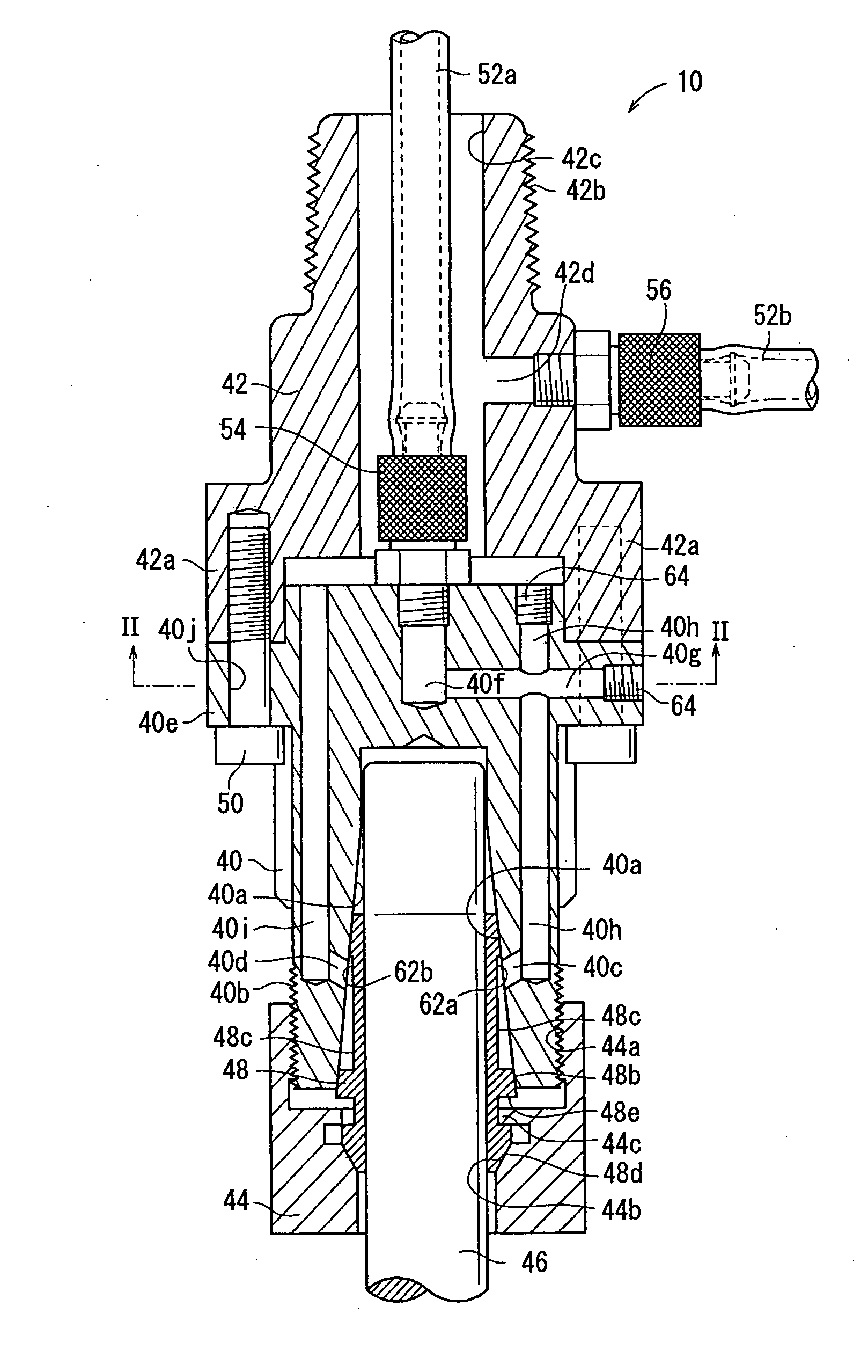
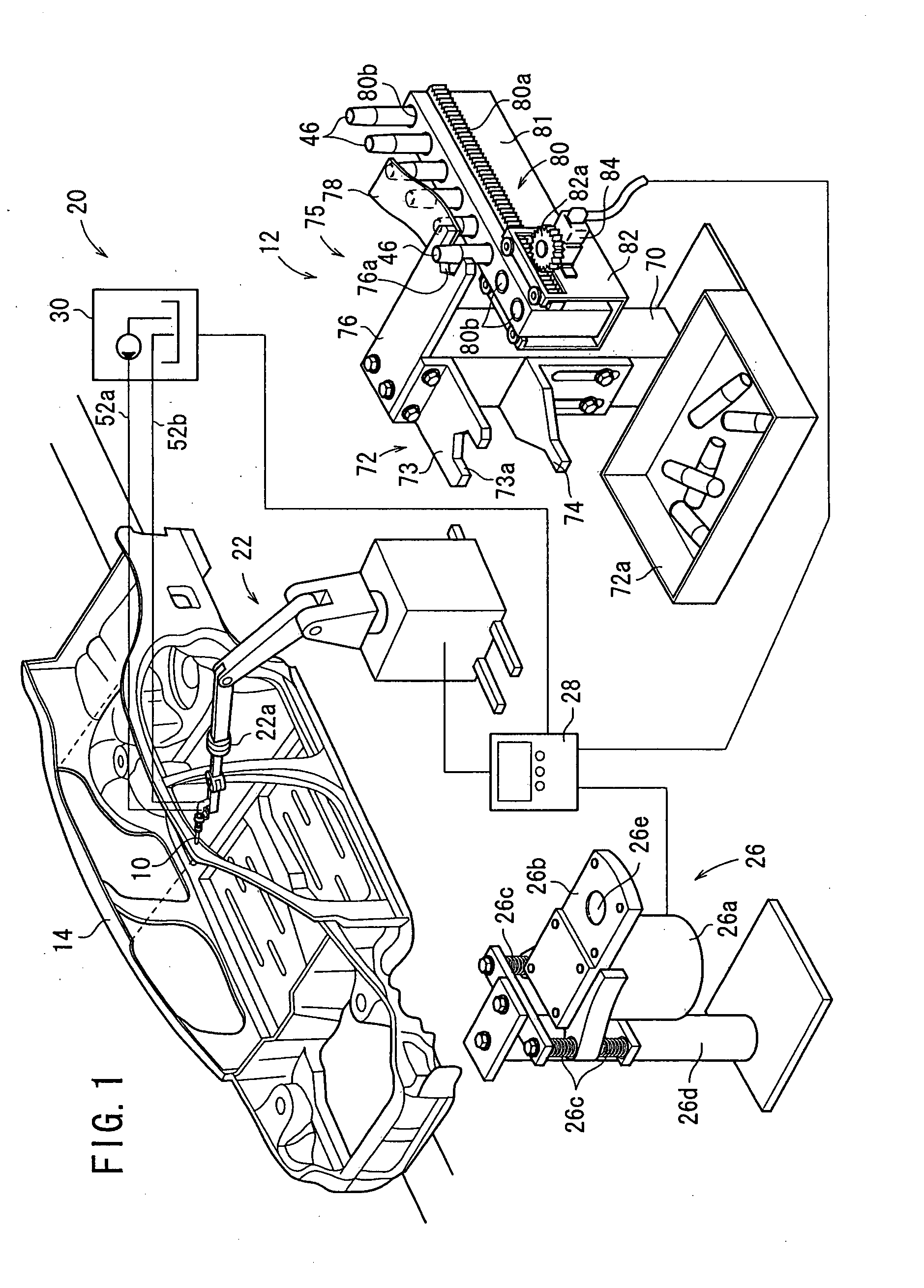
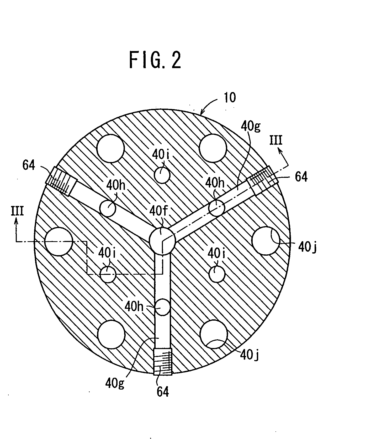
[0040]An electrode tip holder and a welding method according to an embodiment of the present invention will be described below with reference to FIGS. 1 through 13.

[0041]As shown in FIG. 1, an electrode tip holder 10 according to an embodiment of the present invention is incorporated in a welding system 20. A welding method according to an embodiment of the present invention is performed using the welding system 20. The welding system 20 is placed in a process for spot-welding a vehicle frame 14 that is fed along a production line. The welding system 20 has an industrial articulated robot (moving unit) 22 with the electrode tip holder 10 mounted as an end effector on its arm's tip end, an electrode tip adjusting and replacing apparatus 12, a tip dresser 26, and a control device 28 for controlling the welding system 20 in its entirety. The welding system 20 also includes a coolant supply source 30 for supplying a coolant to and retrieving a coolant from the electrode tip holder 10 th...


PUM

PropertyMeasurementUnit
Diameteraaaaaaaaaa
Areaaaaaaaaaaa
Distanceaaaaaaaaaa

Abstract

An electrode tip holder, a welding method, and an electrode tip adjusting device. The electrode tip holder comprises a chuck body having an inner diameter hole with a first tapered inner peripheral surface diverging toward the tip thereof, a lock nut threaded with the tip male screw part of the chuck body, and a collet fitted to the inner diameter hole. The collet is axially pressed since the lock nut is threaded with the tip male screw part and reduced in diameter by the elastic deformation of a slit to hold an electrode tip fitted to the inside thereof. The chuck body comprises a coolant supply port supplying a coolant to a groove part and a coolant recovery port recovering the coolant from the groove part which are opened at positions facing the groove part.

Description

TECHNICAL FIELD[0001]The present invention relates to an electrode tip holder for holding an electric tip for use in an electric welding process, a welding method using an electrode tip, and an electrode tip adjusting apparatus (device) for adjusting and replacing an electrode tip.BACKGROUND ART[0002]Vehicle manufacturing plants, for example, employ industrial robots having electrode tip holders for automatizing most welding operations in order to efficiently perform many spot welding processes on outer vehicle panels and vehicle frames.[0003]Electrode tips mounted on electrode tip holders are inevitably consumed due to electric discharges, etc. as they are used to weld workpieces. It is customary to polish each electrode tip at appropriate time intervals and replace it with a new electrode tip when it is consumed severely. The severely consumed electrode tip may be manually replaced while the robot is being shut off. Since the manual replacement tends to be inefficient as the time ...

Claims


Application Information

Patent Timeline
IPC IPC(8): B23K9/32B23K11/00B23K11/10
CPCB23K11/11B23K11/314B23K11/3018B23K11/318B23K11/3072
Inventor SUGAHARA, TOSHIOTAKASAKI, NORITOSHITAKASAKI, HARUMIAOKI, HIDEO
Owner HONDA MOTOR CO LTD
Learn More