Method for Processing Substrate, Apparatus for Processing Substrate, Method for Conveying Substrate and Mechanism for Conveying Substrate

a technology for conveying substrates and substrates, applied in the direction of instruments, charge manipulation, furnaces, etc., can solve the problems of uneven distribution of gap spacers between two substrates in the bonded substrate, and achieve the reduction of suppressing warping inside the substrate, and reducing the time required for turning over a substrate

Inactive Publication Date: 2008-08-14
MITSUBOSHI DIAMOND IND CO LTD
View PDF6 Cites 23 Cited by
  • Summary
  • Abstract
  • Description
  • Claims
  • Application Information

AI Technical Summary

Benefits of technology

[0020]In a method for processing a substrate and an apparatus for processing a substrate according to this invention, a mother substrate on which a scribe line has been drawn is sucked and held from a main surface using a number of suction members, each of which has a suction surface when the mother substrate is conveyed, and then, the above described suction members respectively rotated almost simultaneously, and thereby, at least two main surfaces of the mother substrate are turned over in the upward and downward direction, and therefore, the area that is required for turning over a substrate becomes small, and the time required for turning over a substrate becomes shorter. In addition, warping that occurs in a substrate when the substrate is turned over can be reduced, and therefore, warping inside the substrate can be suppressed, and thereby, unevenness can be prevented from occurring in the distribution of gap spacers between two substrates in a bonded substrate. Furthermore, it becomes possible to reduce the dimensions of the apparatus that is required for turning over a substrate, and the area for installment of the apparatus can be reduced.
[0021]In the above described method for processing a substrate, in the case where the respective suction members are rotated around rotational axes which are parallel to each other, extend in the longitudinal direction of the suction members and pass through approximately the center portions of the suction members in the width in the direction perpendicular to the longitudinal direction, the substrates can be rotated with a minimal rotational track and warping which occurs in a substrate at the time of rotation can be minimized, and thereby, the substrate can be prevented from being damaged.
[0022]In the above described method for processing a substrate, in the case where a mother substrate is divided in advance into small mother substrates in stripe form, and each of the divided small mother substrates in stripe form is sucked and held by any one suction member...

Problems solved by technology

In addition, as mother substrates which are used for liquid crystal display panels increase in size, warping which occurs in a substrate when this substrate is turned over incre...

Method used


Image

  • Method for Processing Substrate, Apparatus for Processing Substrate, Method for Conveying Substrate and Mechanism for Conveying Substrate
  • Method for Processing Substrate, Apparatus for Processing Substrate, Method for Conveying Substrate and Mechanism for Conveying Substrate
  • Method for Processing Substrate, Apparatus for Processing Substrate, Method for Conveying Substrate and Mechanism for Conveying Substrate

Examples


first embodiment

[0084]In the following, the first embodiment of this invention is described in detail in reference to FIGS. 1 to 7.

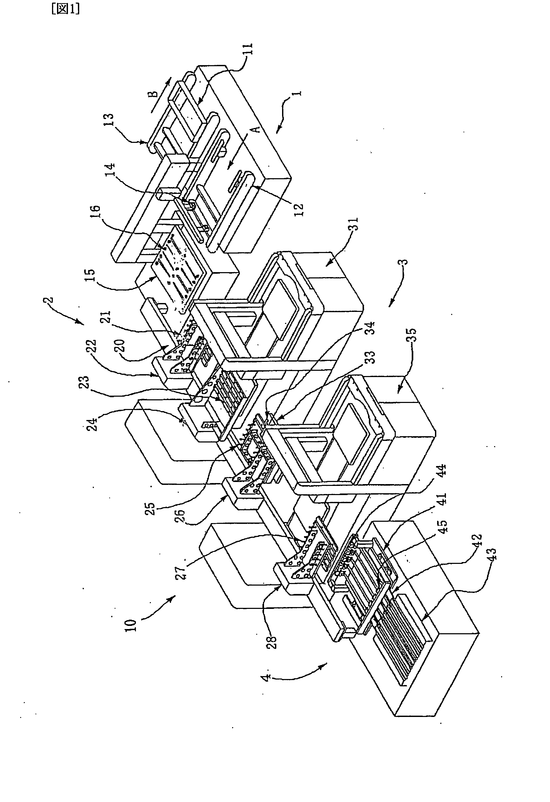
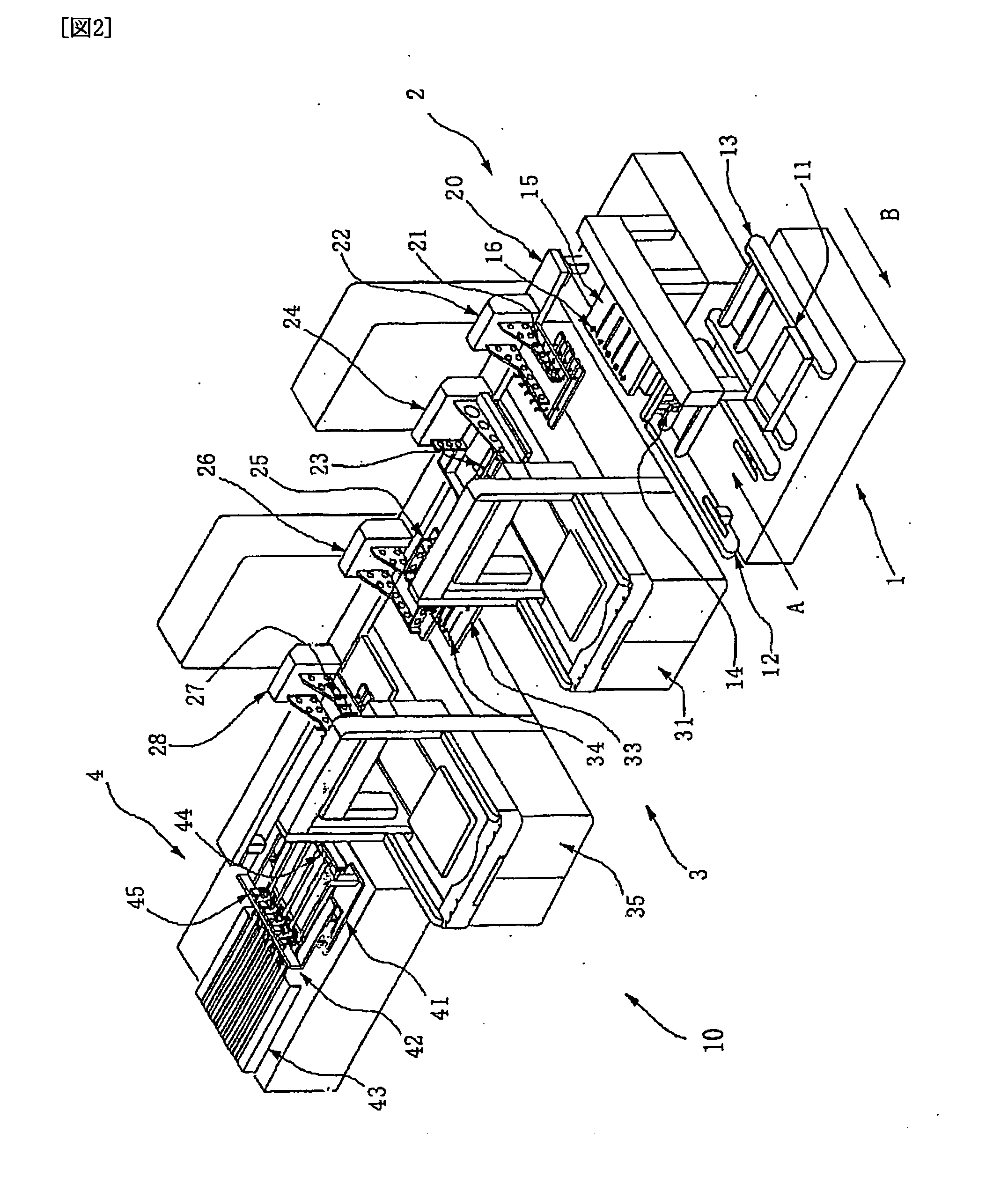
[0085]FIG. 1 is a perspective diagram showing an apparatus for processing a substrate according to this invention as viewed from the left, and FIG. 2 is a perspective diagram showing the above described apparatus for processing a substrate as viewed from the right.

[0086]In FIGS. 1 and 2, an apparatus for processing a substrate 10 is mainly formed of a portion for mounting a substrate 1, where a fragile substrate is mounted, a portion for conveying a substrate 2, having a number of robots for conveying a substrate, a scribing portion 3, which scribes a substrate that has been conveyed by portion for conveying a substrate 2, and a breaking portion 4 for breaking a scribed substrate.

[0087]Examples of the configuration and the operation of apparatus for processing a substrate 10 are described in reference to FIGS. 1 and 2.

[0088]First, a cassette 11 for conveying a substrate...

second embodiment

[0120]In the following the apparatus for processing a substrate according to the second embodiment of this invention is described in reference to FIGS. 8 to 10.

[0121]Though, in the first embodiment, the distance between axis lines of the rotational axis of adjacent suction members is constant in robot for conveying a substrate 24 has suction members so that substrates which are placed on a table in advance at intervals which agree with the distance between the axis lines are sucked and turned over, in the second embodiment, an example of a robot for conveying a substrate having a configuration where the distance between the axis lines of the rotational axis of adjacent suction members is varied in accordance with the intervals of substrates which are mounted on a table in advance and then the substrates which are mounted on the table are sucked and turned over is described.

[0122]As shown in FIG. 8, a portion for turning over and sucking a substrate 70 has a frame 79 having a side pl...

third embodiment

[0134]In the following, the apparatus for processing a substrate according to the third embodiment of this invention is described in reference to FIGS. 11 to 14.

[0135]In the third embodiment, an apparatus for separating a substrate, which separates a substrate along a scribe line, is described as a modification which uses a robot for conveying a substrate 70 having a leaking mechanism 98 in pantograph form as described in the second embodiment.

[0136]That is to say, in the third embodiment, an example of a configuration which has a number of rotational axes to which suction members are attached, a portion for driving a rotational axis, which is the same as those used in the above described first and second embodiments, a frame to which the portion for driving a rotational axis and the number of rotational axes are attached so that the rotational axes can be rotated by the portion for driving a rotational axis, at least one suction member unit formed of a portion for shifting a rotati...


PUM


Abstract

A method for processing a substrate and an apparatus for processing a substrate are provided, where a substrate can be prevented from being damaged during conveyance of the substrate, including turning over of the substrate, and the apparatus for processing a substrate having this mechanism for conveying a substrate is miniaturized, so that the area for installment can be reduced.
[Means for Achieving Object] An apparatus for processing a substrate which divides a mother substrate into unit substrates is provided with a scribing portion 3 for drawing a scribe line on a mother substrate, a breaking portion 4 for breaking a mother substrate along the formed scribe line, and a portion for conveying a substrate 2 for conveying a mother substrate or a unit substrate at least between the above described respective portions, wherein portion for conveying a substrate 2 has a number of rotational supports 51 and 73 with a suction surface for sucking and holding each substrate from a main surface, rotational supports 51 and 73 have rotational axes 52 and 72, respectively, as well as means for respectively sucking and rotating a substrate which rotates substrates around rotational axes 52 and 72, approximately simultaneously in a state where the substrates are sucked and held in such a manner that at least two main surfaces of each substrate are turned over in the upward and downward direction.

Description

TECHNICAL FIELD[0001]This invention relates to a method for conveying a substrate according to which a substrate is turned over and conveyed, an apparatus for conveying a substrate, as well as a method for processing a substrate using this method and apparatus and an apparatus for processing a substrate. The invention particularly relates to a method for processing a substrate according to which a scribe line is drawn on a mother substrate and the above described mother substrate is divided into unit substrates along the drawn scribe line, and an apparatus for processing a substrate.BACKGROUND TECHNOLOGY[0002]In recent years, the use of flat panel displays that are thin and can display in a small display area has been spreading. In liquid crystal display panels, which are one type of panel for such flat panel displays (FPD), two glass substrates are bonded together and liquid crystal is injected into the gap between these, and thus, a display panel is formed. Bonded mother substrate...

Claims


Application Information

Patent Timeline
IPC IPC(8): B65H35/10B26D7/01B26D7/27B26F3/00B28D5/00B65G49/06B65H15/00C03B33/027C03B33/03C03B33/033
CPCB65G49/061B65G49/066C03B33/033C03B33/027C03B33/03B65G2249/04Y10T225/321Y10T225/12Y10T225/30Y10T225/336Y10T225/325C03B33/02G02F1/13
Inventor OKAJIMA, YASUTOMONAKATA, KATSUYOSHI
Owner MITSUBOSHI DIAMOND IND CO LTD
Why Eureka
Try Eureka