Cooling Device for a Light-Emitting Semiconductor Device and a Method of Manufacturing Such a Cooling Device

a cooling device and semiconductor technology, applied in indirect heat exchangers, light-emitting heating devices, laminated elements, etc., can solve the problems of reduced efficiency in converting electric power to light, reduced efficiency in cooling, and reduced efficiency in cooling. , to achieve the effect of efficient cooling and small space requirements

Inactive Publication Date: 2008-08-14
KONINKLIJKE PHILIPS ELECTRONICS NV
View PDF14 Cites 54 Cited by
  • Summary
  • Abstract
  • Description
  • Claims
  • Application Information

AI Technical Summary

Benefits of technology

[0004]An object of the present invention is to provide a cooling device for cooling light-emitting semiconductor devices, the cooling device providing for a small space requirement and efficient cooling.

Problems solved by technology

The high power also results in heat build up in the LED chip.
Such heat build up decreases the efficiency in converting the electric power to light, i.e. decreases the 1 m / W value, and may also cause the destruction of the LED chip due to irreversible thermal damage.
A problem with the lighting arrangement of WO 03 / 096387 is that it is quite complicated and requires quite much space.
This makes it expensive and less useful for applications where space is limited.

Method used


Image

  • Cooling Device for a Light-Emitting Semiconductor Device and a Method of Manufacturing Such a Cooling Device
  • Cooling Device for a Light-Emitting Semiconductor Device and a Method of Manufacturing Such a Cooling Device
  • Cooling Device for a Light-Emitting Semiconductor Device and a Method of Manufacturing Such a Cooling Device

Examples


second embodiment

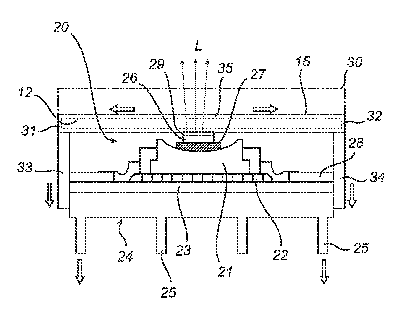
[0049]FIG. 4 illustrates the invention in the form of a ceramic plate 215 made of a translucent ceramic, such as poly crystalline alumina, YAG or AlN. Preferably the ceramic plate 215 comprises a luminescent material. The ceramic plate 215 has elongated channels 212, which are shown in a cross section in FIG. 4. The channels 212 extend in a direction perpendicular to the paper and are connected to heat sinks, not shown in FIG. 4. As shown in FIG. 4 a LED device 220 is partly located inside the actual ceramic plate 215. In the case shown in FIG. 4 a die 226 and a die-attachment glue 227 of the LED device 220 are entirely or almost entirely located inside the ceramic plate 215, while a slug 221, to which the die 226 is attached, is located outside the ceramic plate 215. The LED device 220 further comprises, similar to what is described with reference to FIG. 3, an adhesive 222, a heat spreading board 223, and a cooler 224 having cooling flanges 225.

[0050]The channels 212 have the cros...

third embodiment

[0053]FIG. 5 illustrates the invention in the form of a ceramic plate 315. The ceramic plate 315 is provided with a number of elongated channels 312, shown in cross-section in FIG. 5, that are similar to the channels 12 illustrated in FIG. 2b. The ceramic plate 315 is integrated into a slug 321 of a LED device 320. A die 326 is attached to the ceramic plate 315 by means of a die-attachment glue 327. The LED device 320 further comprises, similar to what is described with reference to FIG. 3, an adhesive 322, a heat spreading board 323, and a cooler 324 having cooling flanges 325. The ceramic plate 315 is made of poly crystalline alumina that is mixed with particles of high index of refraction, such as ZrO2. The particles of high index of refraction provide the ceramic plate 315 with diff-use reflective properties. As alternative coating its upper surface by a whitish ceramic coating could provide such properties. A further possibility is to manufacture the ceramic plate of a cermet, ...


PUM

PropertyMeasurementUnit
lengthaaaaaaaaaa
hydraulic diameteraaaaaaaaaa
translucentaaaaaaaaaa

Abstract

A cooling device for cooling a light-emitting semiconductor device, such as a LED device (20), comprises a ceramic plate (15) having coolant-conveying channels (12) incorporated therein. The ceramic plate (15) is adapted for forming an integral part of the optical system of the light-emitting semiconductor device (20) and to cool a light-emitting portion (26) of the light-emitting semiconductor device (20). A method of forming a cooling device comprises the steps of forming a charge of ceramic particles, embossing the charge with a stamp to form coolant-conveying channels in the charge, hardening the charge, and providing a cover on top of the channels to seal them.

Description

FIELD OF THE INVENTION[0001]The present invention relates to a cooling device for cooling a light-emitting semiconductor device.[0002]The present invention further relates to a method of forming a device for cooling a light-emitting semiconductor device.BACKGROUND OF THE INVENTION[0003]The use of LED's (Light Emitting Diodes) for purposes of solid state lighting, and in particular illumination lighting, is gaining more and more interest. Applications where LED's could be used as a source of illumination lighting, and not just as an indicator lamp, include room lighting, and in particular shopping area lighting, road lighting and automotive lighting, and in particular in automotive headlight applications. Common for all these new applications is that a LED, or often an array of LED's provided on a chip, is operated at a high power to provide the desired light output. The high power also results in heat build up in the LED chip. Such heat build up decreases the efficiency in convertin...

Claims


Application Information

Patent Timeline
Patent Type & Authority Applications(United States)
IPC IPC(8): H01L23/34H01L33/00H01L21/00H01L33/50H01L33/64
CPCF28D15/0233F28D15/0266F28D15/043F28D2021/0029H01L33/648F28F21/04H01L33/50H01L33/641F28F3/12
Inventor DE GRAAF, JANNICOLE, CELINE CATHERINE SARAHVERSCHUUREN, MARCUS ANTONIUSVAN SPRANG, HANSKOP, THEO ARNOLDMARRA, JOHANWOLF, RONALD MARTIN
Owner KONINKLIJKE PHILIPS ELECTRONICS NV
Why Eureka
Try Eureka