Wire and cable dispensing container and systems

a technology for dispensing containers and wires, applied in transportation and packaging, carriage/perambulator with multiple axes, de-stacking articles, etc., can solve the problems of cable kink inside the box, heavy box of cables, and taking some effort to move around

Active Publication Date: 2008-08-14
WINDY CITY WIRE CABLE & TECH PRODS
View PDF25 Cites 43 Cited by
  • Summary
  • Abstract
  • Description
  • Claims
  • Application Information

AI Technical Summary

Benefits of technology

[0009]The present invention permits the easy withdrawal of a length of cable from the cable payout slot formed in the front panel of the carton. When the containers are assembled together in at least one row, an installer may withdraw lengths of cable from each of several containers at once. The heavier reaction mass of the assembled containers permits the installer to pull the cable(s) with more tension, as there will be less of a tendency of the assembled unit (or cart) to move in the direction of pull. When different kinds of cable are to be installed in a run in which the cables will all be of the same length, the present invention permits the installer to withdraw the same length of these different kinds of cable from different containers in the unit or cart, all at the same time.

Problems solved by technology

This conventional method has a drawback in that the cable may kink inside of the box or otherwise resist being pulled out of the box to such an extent that a cable installer or technician finds that he or she is pulling the box across the floor.
These boxes of cable are heavy and it takes some effort to move them around.

Method used


Image

  • Wire and cable dispensing container and systems
  • Wire and cable dispensing container and systems
  • Wire and cable dispensing container and systems

Examples


Embodiment Construction

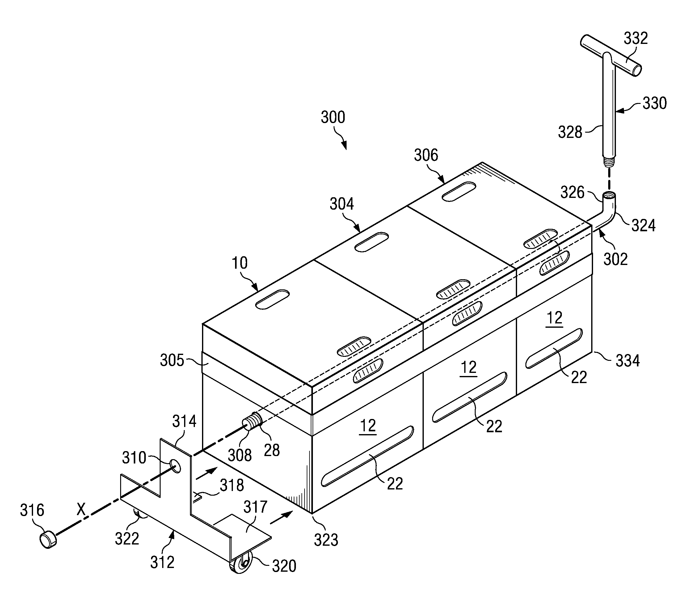
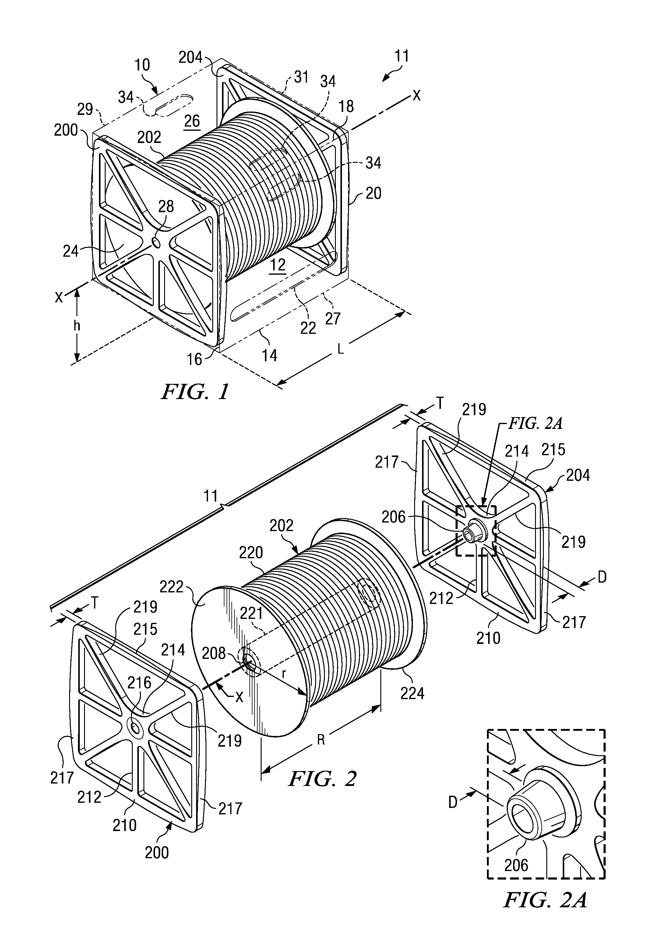
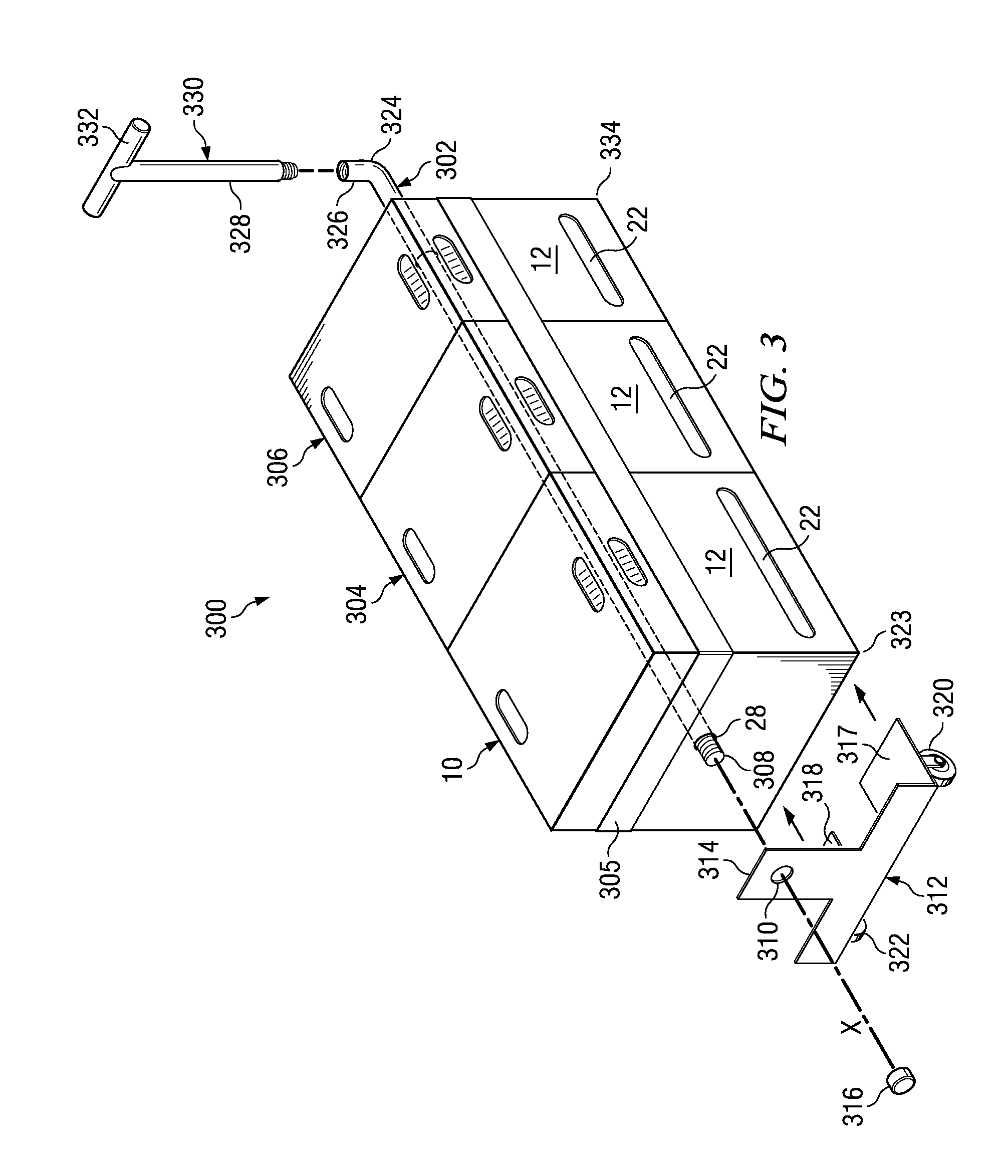
[0025]FIGS. 1 and 2 show a cable reel carton indicated generally at 10, which in turn forms the exterior components of a cable reel container 11. Carton 10 is preferably formed of a single sheet of corrugated cardboard and includes a front panel 12 having a bottom side 14, a left side 16, a top side 18 and a right side 20. The front panel 12 preferably has, in a lower portion thereof, an elongate die-cut cable dispensing or payout slot 22 through which cable or wire may be pulled. The slot 22 is elongate in a direction parallel to a cable reel axis X and is long enough to permit cable to come off the reel at right angles to the reel axis and through the slot 22, no matter where on the reel the cable is presently being unspooled. Preferably the length of the slot 22 is selected to be at least roughly the same as the distance between the internal surfaces of the two cable reel flanges (described below).

[0026]Carton 10 also includes a left panel 24 which extends rearwardly from side 16...


PUM


Abstract

A container for the dispensing of wire or cable has an external carton which receives a reel of cable as supported by two caddies. Each caddy has an inwardly extending substantially cylindrical bushing which is received in a central hole of a respective cable reel flange. The cylindrical bushings are disposed on an axis which is a first distance from the upper surface of the bottom panel of the carton. The largest radius of each reel flange is preselected to be smaller than this such that the reel may freely rotate inside of the carton on the bushings. Cable is pulled through a slot in the carton's front panel. Preferably, left and right panels of the carton each have an arbor hole formed therein which receives an axial rod, the rod also extending through the reel and caddies. The axial rod may be used to join two or more containers together and may further serve as a support for attachment of a wheel truck on one end of the joined-together containers and a handle at its other end. An alternative, four-wheeled cart has multiple axial rods. An alternative hand truck likewise receives multiple axial rods through respective container passageways. In one embodiment, cable may be pulled through one or more pass-through slots formed in the tops and bottoms of stacked containers, such that cable from multiple containers is drawn through one slot on the top of the stack.

Description

BACKGROUND OF THE INVENTION[0001]Wire and cable for installation in residences and buildings typically comes on cable reels. The types of wire and cable so provided are numerous, and include 110V three-conductor wire, “Romex”, and many different kinds of low-voltage, multiconductor insulated communications cable, such as that used for setting up Ethernet networks, intercom systems, entertainment systems and the connection of security sensors and devices. A new building under construction will need many kinds of these cables, and several reels of cable will be used by an installer on-site.[0002]One known technique is to provide coils of such cable in boxes, and to create a hole in a front or top panel of the (typically cardboard) box for pulling out a desired length of cable. This conventional method has a drawback in that the cable may kink inside of the box or otherwise resist being pulled out of the box to such an extent that a cable installer or technician finds that he or she is...

Claims


Application Information

Patent Timeline
Patent Type & Authority Applications(United States)
IPC IPC(8): B65H1/26B65H75/02B62B3/04
CPCB62B1/14B62B3/04B62B5/0083B62B2202/025B62B3/003B65H49/32B65H49/322B65H49/325B65D85/04
Inventor GALGANO, RICHARDWINKEL, MARK K.MCGUIRE, MARTIN C.MCGUIRE, MARTIN J.
Owner WINDY CITY WIRE CABLE & TECH PRODS
Why Eureka
Try Eureka