Pressure Generator for a Vehicle Brake System and Method for Mounting Said Pressure Generator

a technology of pressure generator and vehicle brake system, which is applied in the direction of braking system, liquid fuel engine, mechanical apparatus, etc., can solve the problems of complex construction, and generating high pressure pulsations, and achieves the effects of not being conducive to mounting, reducing the convenience of operation, and reducing the cos

Inactive Publication Date: 2008-08-14
LUCAS AUTOMOTIVE GMBH
View PDF14 Cites 24 Cited by
  • Summary
  • Abstract
  • Description
  • Claims
  • Application Information

AI Technical Summary

Benefits of technology

[0006]It has been found that greater convenience of operation ensues if the conventional (single-piston) pumps are replaced by multi-piston pumps. In the latter, the individual pistons can be activated asynchronously, so that pressure pulsations are markedly smoothed as a result of the superposition of intake strokes and pressure strokes of the individual cylinder/piston arrangements.
[0007]As a result of the plurality of pump pistons however, known multi-piston pumps frequently have a complex construction and one which is therefore cost-intensive and not very conducive to mounting, especially as said pump pistons have to be accommodated in a manner appropriate to the drive and a large number of connecting ducts, both between the individual cylinder/piston arrangements and also to fluid connections, frequently have to be constructed. But even in the case of single-piston pumps, mounting and, above all, the replacement of the pressure generator is not simple.
[0008]The underlying object of the invention is to indicate a pressure generator of the single-piston or multi-piston type, and one which can be mounted easily. Another underlying object of the invention is to indicate a method for mounting the pressure generator.
[0009]According to a first aspect of the invention, this object is achieved by means of a pressure generator for a vehicle brake system, comprising a pump subassembly, which can be handled individually (separately), with a cylinder block with at least one inlet for a hydraulic fluid and at least one outlet for said hydraulic fluid, wherein in said cylinder block one, two or more cylinders are arranged, in each of which a pumping piston is received, and with an actuating unit for said pumping pistons. The pressure generator further comprises a housing for receiving, at least partially

Problems solved by technology

In the case of conventional pumps, however, it has been observed that these generate high pressure pulsations when regulating interventions occur.
Pressure pulsations of this type reduce the convenience of operation in some situations, since they are interpreted by the driver as malfunctioning and, moreover, are frequently accompanied by unpleasant noises.
As a result of the plurality of pump pistons however, known multi-piston pumps frequently have a complex const

Method used


Image

  • Pressure Generator for a Vehicle Brake System and Method for Mounting Said Pressure Generator
  • Pressure Generator for a Vehicle Brake System and Method for Mounting Said Pressure Generator
  • Pressure Generator for a Vehicle Brake System and Method for Mounting Said Pressure Generator

Examples


first embodiment

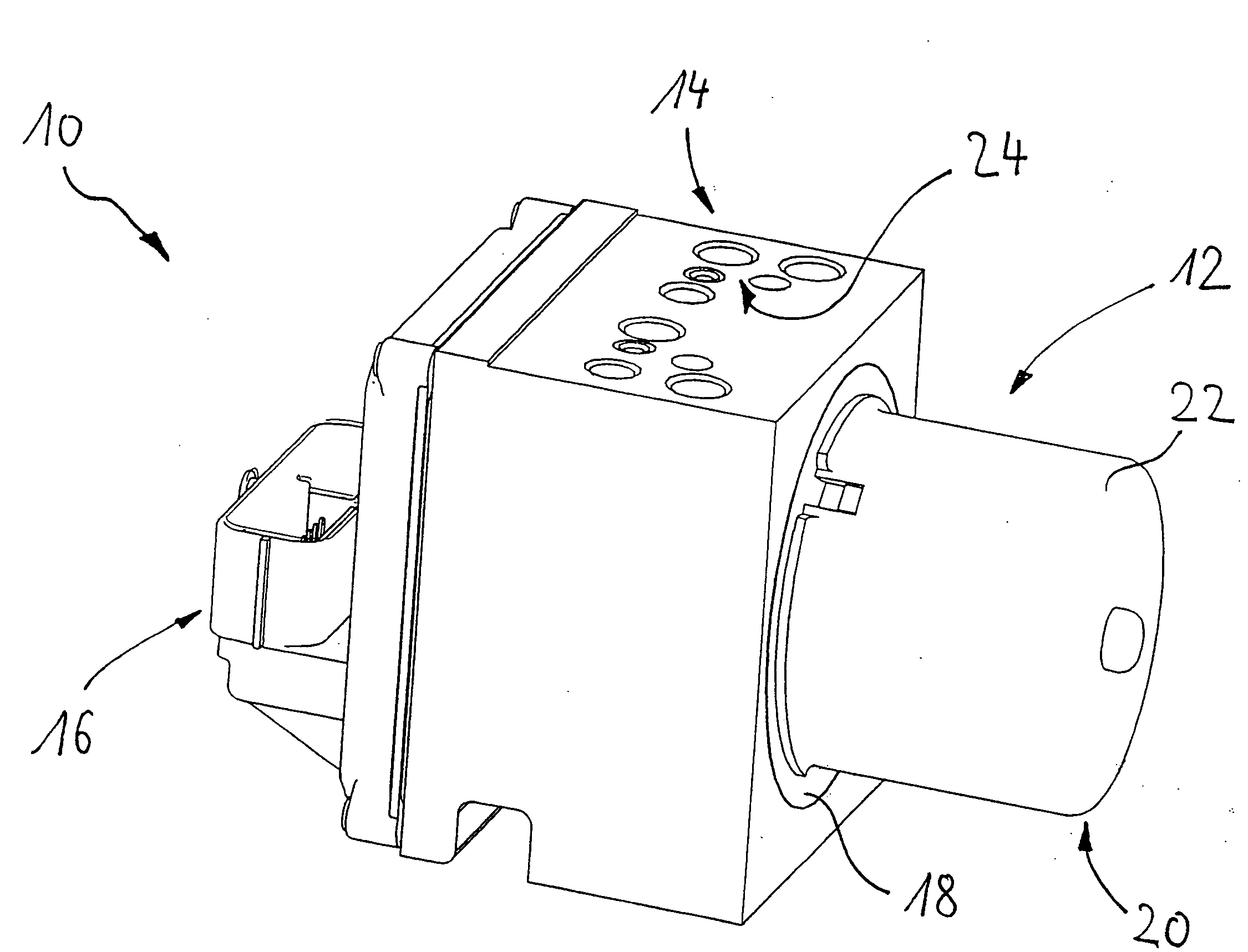
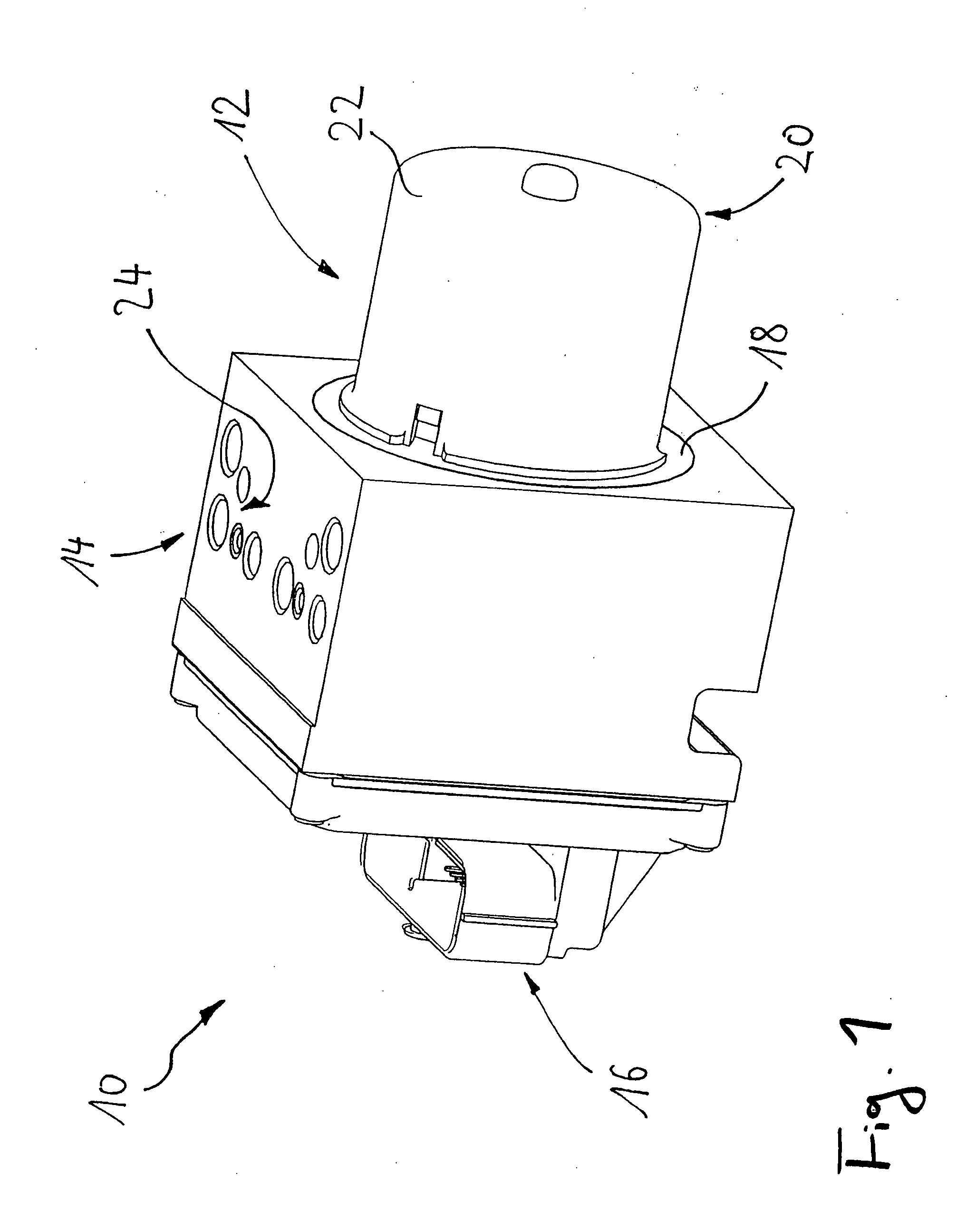
[0046]FIG. 1 shows a perspective view of a pressure generator 10 according to the invention for a vehicle braking system, in the finally assembled state. Said pressure generator 10 is suitable, for example, for implementing a VSC regulating apparatus.

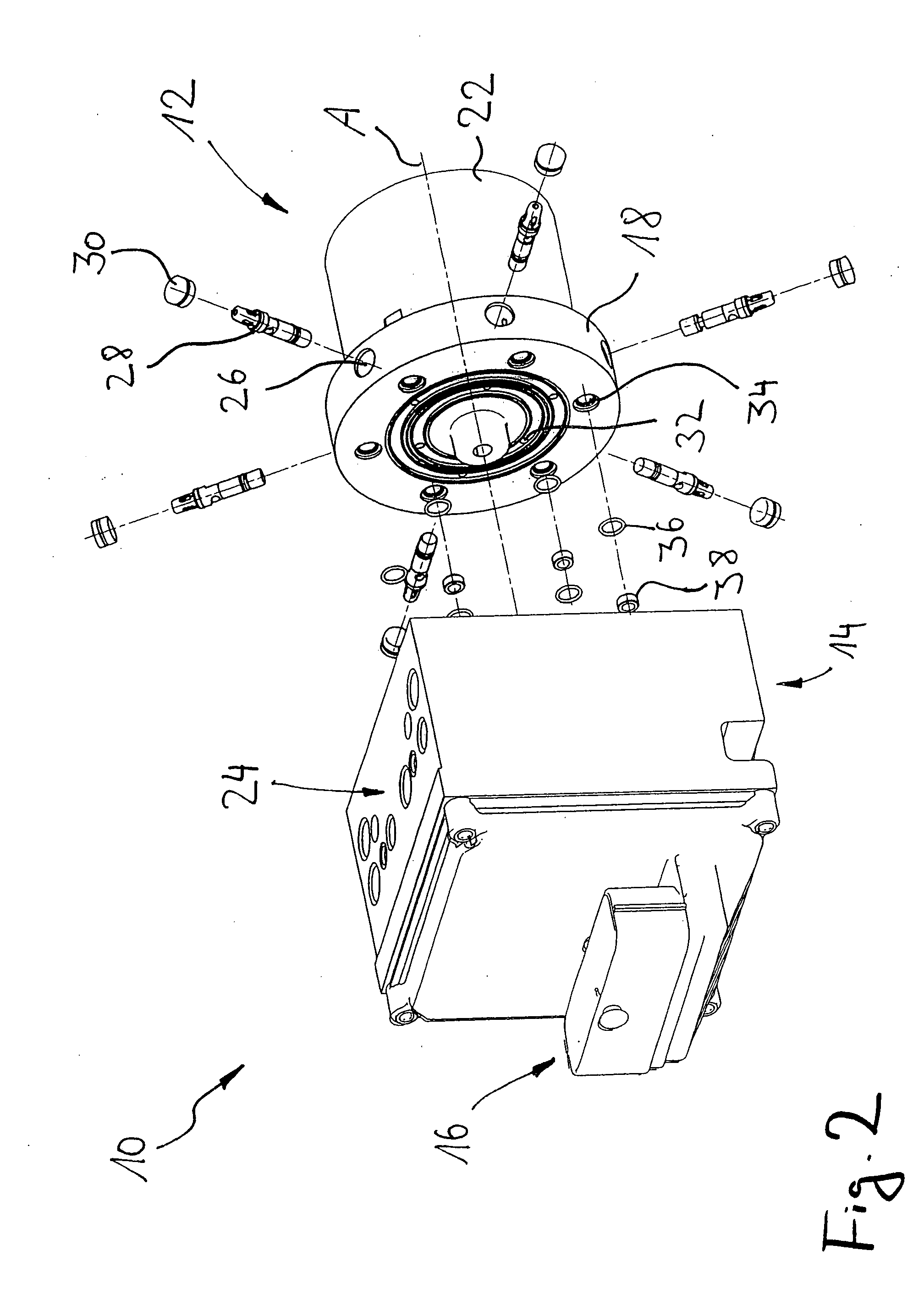
[0047]The pressure generator 10 according to FIG. 1 comprises a pump subassembly 12 which can be handled separately and which is received, partially, in a receiving housing 14 in the form of a solid aluminum block with fluid lines constructed therein and fluidics control elements arranged therein. The pressure generator 10 comprises, as the third main component, a unit 16, which is screwed onto the housing 14, for making contact with the electrical components of the pressure generator 10.

[0048]The pump subassembly 12, which is partially inserted in the housing 14, comprises a circular-ring-shaped cylinder block 18, which is only partly visible in FIG. 1 and is made of a wear-resistant material such as steel or grey cast iron, and also a...

second embodiment

[0063]As emerges from the perspective view of the pump subassembly 12 in the second embodiment according to FIG. 7, the actuating unit 20 has an electrical connection 50 which is routed out of the housing 22 of said actuating unit 20. Said electrical connection 50 serves to supply an electric motor (not represented in FIG. 7), which is arranged in the housing 22 of the actuating unit 20, with electric power.

[0064]In contrast to the first embodiment, in the case of the pump subassembly 12 in the second embodiment, the fluid outlets 34 are arranged on the outer periphery of the annular cylinder block 18 and adjacent to the appertaining cylinder apertures 26. The fluid inlets 32 in the cylinder block 18 are constructed on that end face of the cylinder block 18 which faces towards a receiving housing, which is not represented, for the pump subassembly 12. This situation can be inferred from the front view of the subassembly according to FIG. 9, while FIG. 8 shows a rear view. It can als...


PUM


Abstract

What is described is a pressure generator for a vehicle brake system and also a method for mounting said pressure generator in said vehicle brake system. The pressure generator possesses a modular construction consisting of a pump subassembly and a receiving housing for said subassembly. The housing is designed in such a way that it has at least one fluid connection which, when the pressure generator is in the mounted state, is connected to a fluid inlet or a fluid outlet on a cylinder block belonging to the pump subassembly. Said pump subassembly is preferably constructed as a multi-piston pump and may comprise an actuating unit for the asynchronous actuation of the pumping pistons.

Description

CROSS-REFERENCE TO RELATED APPLICATIONS[0001]This application is a National Stage of International Application No. PCT / EP2005 / 013028 filed Dec. 5, 2005, the disclosures of which are incorporated herein by reference, and which claimed priority to German Patent Application No. 10 2004 058 726.4 filed Dec. 6, 2004, the disclosures of which are incorporated herein by reference.BACKGROUND OF THE INVENTION[0002]The invention relates to a pressure generator for a hydraulic or electrohydraulic vehicle brake system. The invention also relates to a method for mounting the said pressure generator.[0003]Modern hydraulic or electrohydraulic vehicle brake systems require reliable pressure generators in order to be able to implement systems which are relevant to safety, such as a hydraulic brake-force booster system, an anti-locking system (ABS), a distance-regulating system (ACC) or a drive-slip-regulating system (ASR). In these systems, a hydraulic pressure is generated by means of a pressure ge...

Claims


Application Information

Patent Timeline
IPC IPC(8): B60T8/40F04B1/00
CPCB60T8/368B60T8/4022F04B53/16F04B1/053F04B17/03F04B1/0404
Inventor GIERING, WILFRIEDSEIBERT, WERNEROHLIG, BENEDIKTGILLES, LEOKNECHTGES, JOSEF
Owner LUCAS AUTOMOTIVE GMBH
Why Eureka
Try Eureka