
Method and device for production and emission of a high-power microwave pulse

a high-power microwave and microwave pulse technology, applied in pulse generators, pulse techniques, instruments, etc., can solve the problems of reducing the space required for hardware to about two thirds of that previously required, and avoiding complexity, so as to speed up the process of discharging the series circuit, improve the radio-frequency oscillation response, and reduce the charging resistance

Inactive Publication Date: 2008-08-14
DIEHL BGT DEFENCE GMBH & CO KG
View PDF7 Cites 12 Cited by
  • Summary
  • Abstract
  • Description
  • Claims
  • Application Information

AI Technical Summary

Benefits of technology

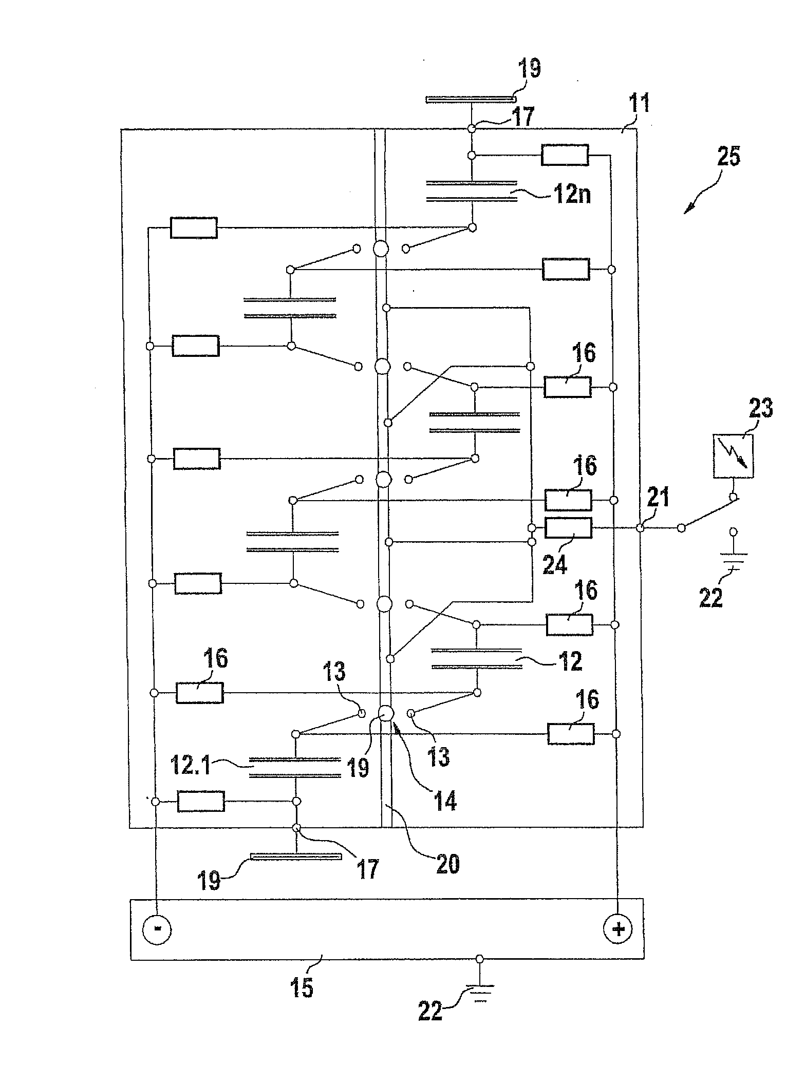
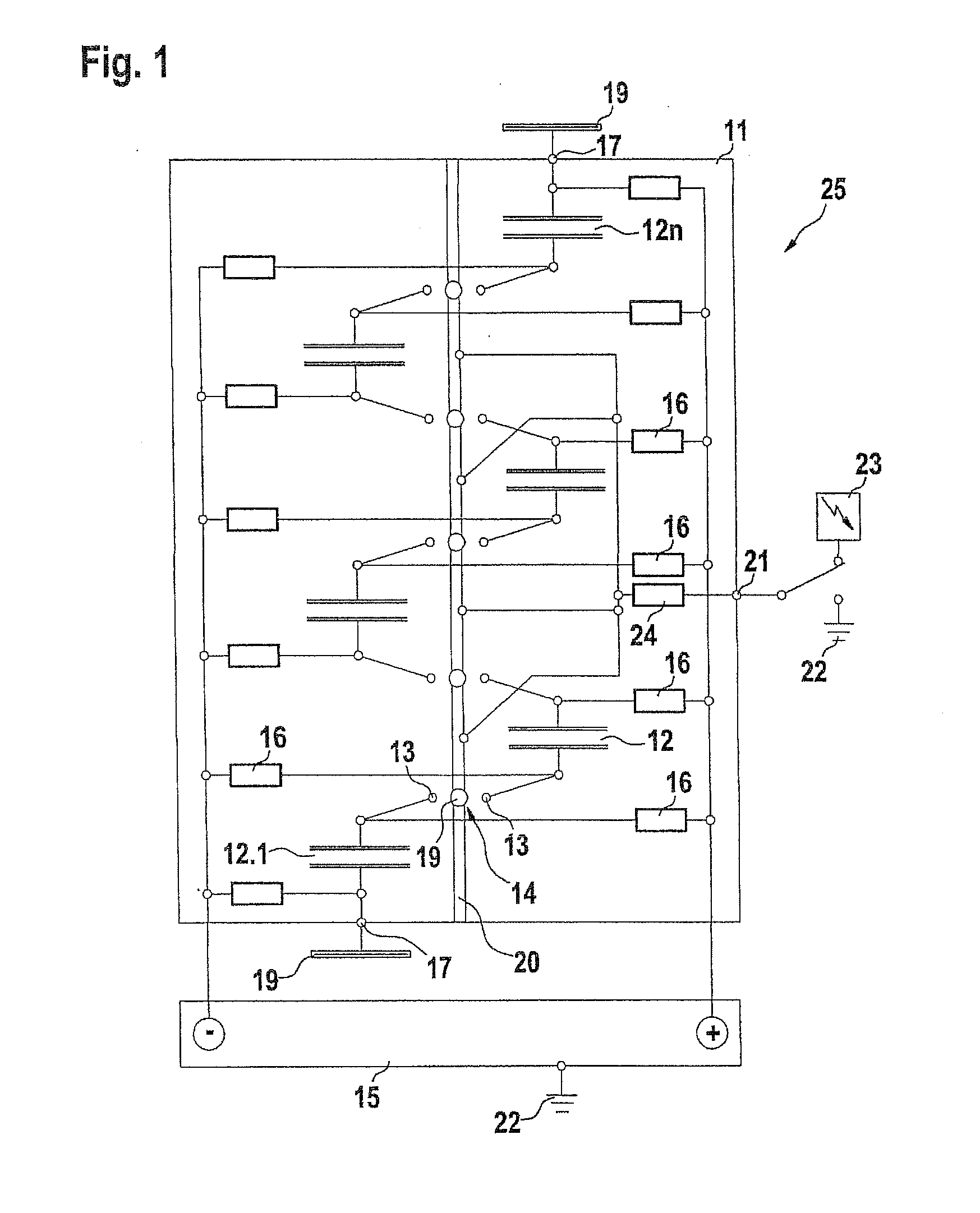
[0005]This object is achieved by the present disclosure in that any microwave generator connected downstream from the Marx pulsed-voltage generator and with an antenna for production and emission of pulsed energy is completely dispensed with, and, instead of this, the microwave energy is now produced and emitted by the Marx pulsed-voltage generator itself, which for this purpose acts as a resonator and capacitively-fed Hertzian dipole with large stray capacitances. This saves the complexity for production of a separate microwave generator fitted with an antenna, with its additional spark gaps, thus reducing the space required for the hardware to about two thirds of that previously required.
[0009]The use of externally triggerable spark-gap switches for each of the capacitor stages in the Marx generator is particularly advantageous for an oscillation response which starts steeply. This avoids one spark gap being triggered only when the preceding stage in the capacitor column has been triggered, which would typically lead to a switching delay of approximately 1 ns per stage. The central triggering of all of the spark-gap switches at the same time in contrast ensures that, because of the simultaneous switching of all of the capacitor stages of parallel charging to series discharging, there is virtually no loss of charge over their individual charging resistors, but the entire voltage from the series circuit of all of the capacitor stages with the respective triggered spark gaps located between them is now actually directly available for excitation of the radio-frequency resonance effect across the capacitor columns, and this leads to the emission of a steeply rising, high-energy microwave pulse directly from the Marx generator.
[0010]In this context, it is particularly expedient to use spark-gap switches which each have a third electrode as the trigger electrode. These trigger electrodes can all be interconnected and can be connected via a series resistance to earth potential, while the capacitor stack is charged in a bipolar form (balanced with respect to earth potential). When the first of the spark gaps is triggered, the trigger electrodes on all of the other spark gaps are therefore at one of the two charge potentials with respect to earth potential so that they are therefore all triggered immediately. The greater the number of such switching processes that have already taken place, the greater is the potential difference across the switching gaps that still remain, so that these now respond even more reliably, and are triggered more quickly.
[0011]The electrically interconnected trigger electrodes may, however, also all be driven jointly from a high-voltage pulse generator which is operated especially for this purpose. When the trigger electrodes are connected in series, its trigger pulse would pass over the entire length of the stack of capacitors that have just been charged in order now to discharge them in series, but with a delay time in the order of magnitude of typically one nanosecond over a path length in the order of magnitude of 30 cm. The switching synchronicity can therefore be improved further if the trigger pulses are fed in more than once, symmetrically, to the trigger electrodes so that the effective delay times of the trigger pulses are significantly shortened by fanning them out directly to the spark gaps.

Problems solved by technology

This saves the complexity for production of a separate microwave generator fitted with an antenna, with its additional spark gaps, thus reducing the space required for the hardware to about two thirds of that previously required.

Method used


Image

  • Method and device for production and emission of a high-power microwave pulse
  • Method and device for production and emission of a high-power microwave pulse

Examples


Embodiment Construction

[0014]The Marx pulsed-voltage generator which is referred to in the following text here for the sake of simplicity as a Marx generator 11, has a column comprising n relatively large-volume capacitors 12 (12.1 to 12.n), which, in the interest of high-density design are stacked, as shown in the sketch, offset laterally with a gap in a zigzag form to form a short column. A high-voltage switch, in the form of the two electrodes 13-13, which must be oriented with respect to one another, of a spark gap 14 is connected in series with in each case two mutually associated capacitors 12-12.

[0015]The capacitors 12 are each charged in parallel from a direct-current charging circuit 15 with a preferably bipolar high voltage in the order of magnitude of several tens of kilovolt, with a charging current in the order of magnitude of one milliampere. Each capacitor 12 is preceded by a respective decoupling resistor 16 in each of its two charging paths, preventing short-circuits via these charging pa...


PUM


Abstract

The production and emission of high-energy microwave pulses are made possible by means of a device with a particularly compact design if the capacitor column (12-12) of the Marx generator (11) whose series circuit conventionally itself feeds a microwave generator with a matched antenna geometry, is now itself used—dispensing with the microwave generator and its antenna—directly as a resonator and Hertzian antenna dipole (24). Its oscillation response can be optimized by triggered spark gaps (14) for the switching of capacitors (12), and by means of plates (19) connected at the ends, in order to increase the stray capacitances.

Description

BACKGROUND OF THE INVENTION[0001]1. Field of the Invention[0002]The invention relates to a method for the production and emission of a high-power microwave pulse. Furthermore, the invention provides for a device for the production and emission of a high-power microwave pulse.[0003]For example, DE 1 03 19 475 A1 describes a generator for production and emission of pulsed energy in the microwave spectrum (generally referred to as HPM=High Power Microwaves), whose energy density with a broader bandwidth is suitable for at least adversely affecting radio traffic being operated in the vicinity and, in particular, for interfering with the input side, or even destroying, electronic circuits. For this purpose, the microwave generator uses an antenna structure that is matched to it to emit pulsed energy. The microwave generator is energized from a charging circuit with an electrical power source, in the case of mobile appliances a rechargeable battery, and with an electronic voltage converte...

Claims


Application Information

Patent Timeline
Patent Type & Authority Applications(United States)
IPC IPC(8): H03K3/00
CPCH03B11/02F41H13/0068
Inventor STAINES, GEOFFREY
Owner DIEHL BGT DEFENCE GMBH & CO KG
Learn More