Backlight Device and Liquid Crystal Display Device

a liquid crystal display and backlight technology, applied in the field of backlight devices, can solve the problems of reducing the brightness of the front surface, drastically lowering the front surface brightness, and difficult to evenly mix the colors on the light transmitting/diffusing plate, so as to reduce the variations in color or brightness, and reduce the thickness of the backlight device

Active Publication Date: 2008-08-14
SATURN LICENSING LLC
View PDF5 Cites 19 Cited by
  • Summary
  • Abstract
  • Description
  • Claims
  • Application Information

AI Technical Summary

Benefits of technology

[0022]According to the present invention, the subjacent type backlight device, illuminating the liquid crystal display panel, includes a light source arranged in a casing opened in a light radiating surface, so that the light source faces the light radiating surface, with the light source radiating light towards the light radiating surface, light transmitting reflecting means arranged in the casing for delimiting a space inclusive of the light source, with the light transmitting reflecting means transmitting a fraction of the incident light and for reflecting another fraction of the incident light, and transmitting diffusing means arranged on the light radiating surface of the casing for diffusing the light transmitted through the light transmitting reflecting means and for causing surface light radiation.
[0023]On the inner surface of the casing, there is provided a reflecting surface for reflecting the incident light, and a portion of light radiated from the light source is internally reflected by the light transmitting reflecting means and by the reflecting surface in the space delimited in the casing by the light transmitting reflecting means. The light portion is then transmitted through the light transmitting reflecting means for surface light radiation.
[0024]By so doing, the portion of light radiated from the light source is repeatedly reflected in the space delimited in the casing by the transmitting reflecting means so as to be then transmitted through the light transmitting reflecting means to fall on the transmitting diffusing means. Consequently, the light radiated from the light source is spread to a wide zone before being incident on the transmitting diffusing means, so that, even in case the distance between the light source and the transmitting diffusing means is decreased to reduce the thickness of the backlight device, there may be obtained the favorable effect in diminishing the variations in color or brightness in surface light radiation from the light source which is equivalent to that in case the light source and the transmitting diffusing means are separated apart sufficiently from each other.
[0025]Viz., in case the red light emitting diode, emitting red light, the green light emitting diode, emitting green light and the blue light emitting diode, emitting blue light, are used as the light sources, the conventional practice has been to separate the light sources and the transmitting diffusing means sufficiently for mixing the colors of the light to yield white color light diminished in variations in color or brightness. According to the present invention, in which the light transmitting reflecting means is provided within the casing, it is possible to reduce the variations in color or brightness without providing for the sizable separation between the light source and the transmitting diffusing means.
[0026]If, in case the light source is the fluorescent tube, the separation between the fluorescent tube and the transmitting diffusing means is diminished to reduce the thickness of the backlight device, by providing the light transmitting reflecting means in the casing, it is possible to prevent the shade of the fluorescent tube from falling on and affecting the transmitting diffusing means to diminish the variations in color or brightness further.
[0027]Moreover, when the light transmitting reflecting means is provided in the casing, the light radiated from a given light emitting diode is spread over a wide area before being incident on the transmitting diffusing means, and hence the light radiated from the light source may be prevented from being locally incident on the transmitting diffusing means, with the result that the number of light sources used may be reduced to lower the cost significantly.

Problems solved by technology

However, even if ideal perfect scattering is realized by the light transmitting diffusion plate 53, as a result of the aforementioned processing for adjusting the angle of diffusion or for patterning, there still persists the problem that an image of a light source on the light transmitting diffusion plate 53 cannot completely be erased, in case the distance between the fluorescent lamps 51, emitting the white light, and the light transmitting diffusion plate 53, is short, that is, if the backlight box 50 is not of a sufficient thickness.
Moreover, if the light transmitting diffusion plate 53 is of an enlarged angle of diffusion, or is subjected to preset patterning, as described above, there may be raised a further problem that the light volume of the component in the vertical direction of the white light from the backlight box 50 with respect to the liquid crystal display panel is excessively attenuated, thus drastically lowering the front-surface brightness.
It is therefore extremely difficult to mix the colors evenly on the light transmitting / diffusing plate 63 such as to preclude variations in color or in brightness.
Hence, the backlight box 60, employing the light emitting diodes 61 as the light source, suffers from the problem that it is further deterrent to reducing the thickness of the liquid crystal device.

Method used


Image

  • Backlight Device and Liquid Crystal Display Device
  • Backlight Device and Liquid Crystal Display Device
  • Backlight Device and Liquid Crystal Display Device

Examples


first embodiment

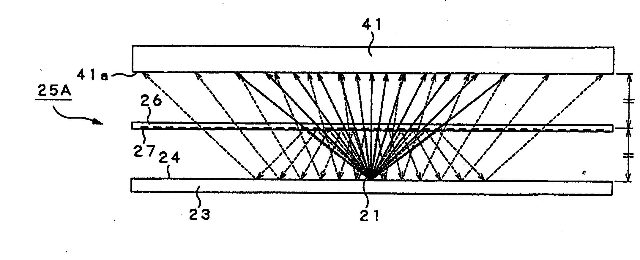
[0071]First, as the light transmitting / reflecting plate 25, such a light transmitting / reflecting plate 25A, comprised of a full transmitting plate 26, on one major surface 26a of which a plural number of dot-shaped total reflection mirrors 27, adapted for reflecting the light, incident at a preset angle of incidence, by total reflection, are formed by patterning, as shown in FIG. 10, may be thought of. The full transmitting plate 26 is a plate-shaped or film-shaped transparent member, formed of, for example, acrylic resin or polycarbonate, and which is adapted for transmitting the incident light in its entirety. The number of the total reflection mirrors 27 on the full transmitting plate 26 is determined by the proportions of transmission and reflection of the light incident on the light transmitting / reflecting plate 25.

[0072]Referring to FIG. 11, the light transmitting / reflecting plate 25A is arranged at a location about halfway between the reflective surface 24 on the bottom of th...

second embodiment

[0083]The light transmitting / reflecting plate 25 may be configured as a light transmitting / reflecting plate 25B, formed by a multi-layered dielectric film on a substrate, which multi-layered dielectric film is comprised of at least one thin film of a low refractive index material and at least one thin film of a high refractive index material, thereby controlling the reflectance (transmittance). The reflectance may be optionally adjusted by the components of the low refractive index material and the high refractive index material, and / or the number of the thin films.

[0084]Similarly to the light transmitting / reflecting plate 25A, shown in the first embodiment, this light transmitting / reflecting plate 25B is arranged at a position approximately halfway between the reflective surface 24 on the bottom surface of the box casing 23 and the light incident surface 41a of the light transmitting / diffusing plate 41, within the box casing 23 of the backlight box 40, as shown in FIG. 13.

[0085]Wit...

third embodiment

[0096]As the light transmitting / reflecting plate 25, a light transmitting / reflecting plate 25C, shown in FIG. 14, may be thought of. The light transmitting / reflecting plate 25C represents the combination of the first and second embodiments. Specifically, a number of multi-layer dielectric films 28, each made up by a layered assembly of a thin film formed of a low refractive index material and a thin film of a high refractive index material, both controlled as to reflectance (transmittance), are formed as dots, by patterning, similarly to the total reflection mirrors 27, on the full transmitting plate 26, used with the light transmitting / reflecting plate 25A.

[0097]This light transmitting / reflecting plate 25C has the merits of the light transmitting / reflecting plate 25A and of the light transmitting / reflecting plate 25B in combination. That is, similarly to the light transmitting / reflecting plate 25B, the light transmitting / reflecting plate 25C is able to diffuse the light, transmitte...


PUM

PropertyMeasurementUnit
reflectanceaaaaaaaaaa
thicknessaaaaaaaaaa
thicknessaaaaaaaaaa

Abstract

A backlight device includes a light source (21) arranged in a casing (23) opened in a light radiating surface (20a), so that the light source faces the light radiating surface (20a) and radiates light towards the light radiating surface (20a), a light transmitting reflecting plate (25) arranged in the casing for delimiting a space inclusive of the light source (21) and adapted for transmitting a fraction of the incident light and for reflecting another fraction of the incident light, and a light transmitting diffusing plate (41) arranged on the light radiating surface (20a) of the casing (23) for diffusing the light transmitted through the light transmitting reflecting plate (25) and for causing surface light radiation. A light reflecting surface (24) is formed on the inner surface of the casing (23). A portion of light radiated by the light source (21) is internally reflected by the light transmitting reflecting plate (25) and by the light reflecting surface (24), in a space delimited in the casing (23) by the light transmitting reflecting plate (25), after which the light portion is transmitted through the light transmitting reflecting plate (25).

Description

TECHNICAL FIELD[0001]This invention relates to a backlight device for a liquid crystal display (LCD) device. More particularly, it relates to a backlight device of a thin thickness and a liquid crystal display device employing this backlight device.[0002]The present invention contains subject matter related to Japanese Patent Application 2004-176147 filed in Japan on Jun. 14, 2004, the entire contents of which are incorporated herein by reference.BACKGROUND ART[0003]Television receivers of very thin thicknesses, such as a liquid crystal display device (LCD) or a plasma display panel (PDP), have been devised and put to practical use to take the place of the cathode ray tube (CRT) which has long been used since the start of television broadcasting. In particular, the liquid crystal display device, employing a liquid crystal display panel, is a highly promising display type and is expected to become widespread in time to come because it permits driving at low power usage and a large si...

Claims


Application Information

Patent Timeline
Patent Type & Authority Applications(United States)
IPC IPC(8): G02F1/13357F21S2/00F21V3/00F21V7/00F21V7/05F21Y103/00
CPCG02F1/133603G02F1/133605G02F2203/09G02F1/133611G02F1/133609G02F1/1335
Inventor ODAKE, RYOTAKAWASHIMA, TOSHITAKAMORO, SHUJIOKITA, HIROYUKI
Owner SATURN LICENSING LLC
Why Eureka
Try Eureka